THAT Home Automation Topology
The Open Home Automation and Control System
« THAT Network Interface »
- Introduction
- THAT Overview
- THAT Hardware
- Power Supply
- Network Interface
- Digital Thermostat Module
- Electronic Access Module
- THAT Control Software
- Capstone Project Deliverables
Overview:
An Ethernet controller (also known as a Network Interface or NIC) is a "sub-module" which every THAT module must contain. It is likely that many THAT modules will make use of identical or very similar NIC designs. This page documents the latest version of my NIC design.
The main purpose of the NIC is to use an Ethernet controller IC to implement low-level network functions in hardware. Additionally, the NIC contains the physical connection port and all the magnetics (transformers and chokes) to complete the IEEE 802.3-compliant network interface.
Schematics:
The latest schematic for the NIC is shown below. Some notes about this design can be found following the schematic.
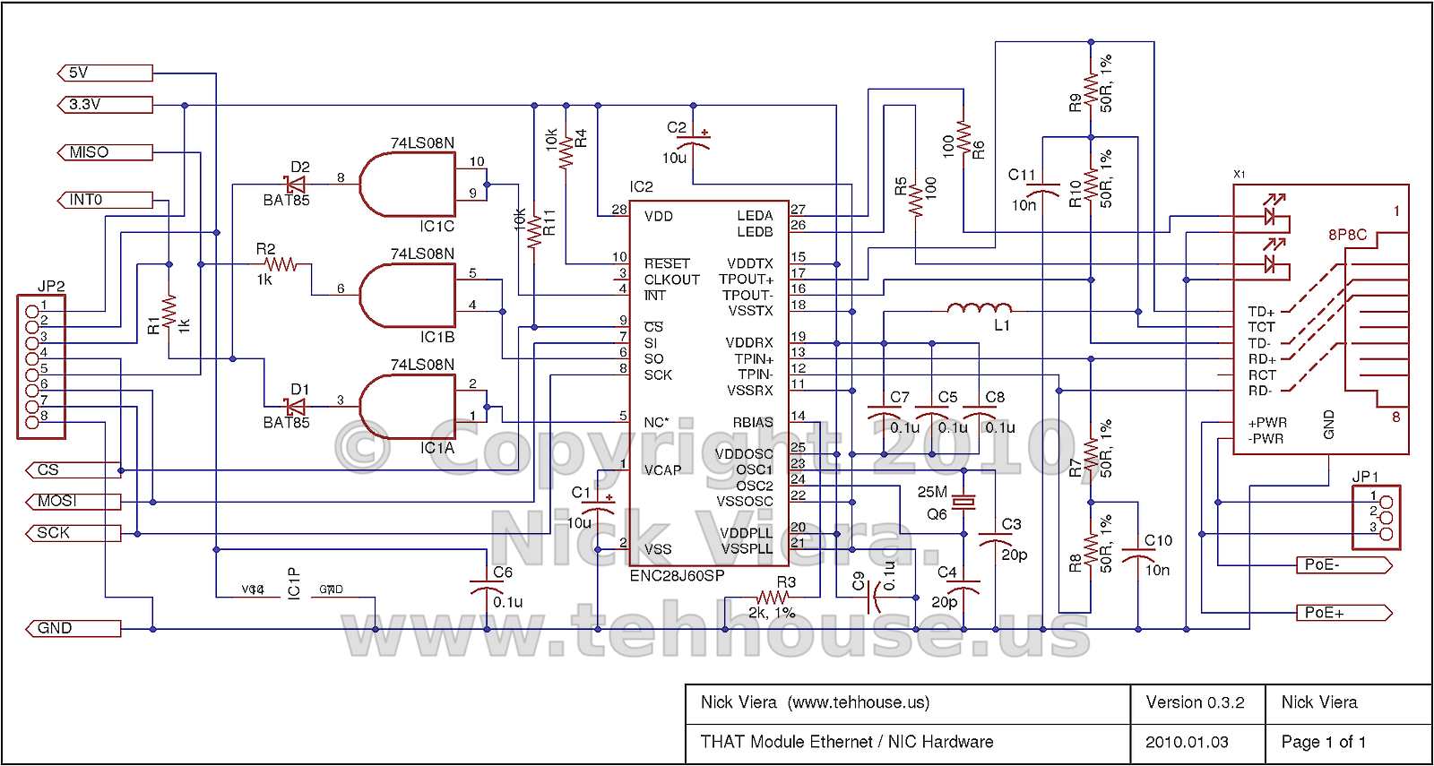
Notes:
- The modular jack (Digikey P/N A99644-ND) contains the necessary additional components for proper IEEE 802.3 support. These include two 1:1 center-tapped transformers, matched chokes, and bridge rectifiers needed to capture PoE power. The jack also includes two LEDs which will be used to indicate network link and activity.
- The AND Gate (IC1) is being used as a buffer to convert the ENC28J60 3.3 Volt outputs to 5 Volt logic. If the microcontroller is operated at 3.3 Volts, this IC as well as D1 and D2 can be omitted.
- The ENC28J60 uses a 25 MHz crystal to drive its internal oscillator. It can then output a clock signal of various speeds using an internal divider / prescaler. In a future version this clock output may be fed into the microcontroller's XTAL1 pin to provide it with a clock (depending on final voltage and speed requirements.)
- The 50-ohm, 1% tolerance resistors for R7-R10 are (apparently) difficult to find. Substitutions of 49.9, 51, or similar resistances have been found to work.
- The choke L1 is ill-defined. The ENC28J60 datasheet only suggests that the choke must be rated to carry at least 80mA. Guido Socher from tuxgraphics.org reports that a handful of turns around a 5mm ferrite bead works well. We chose to use a 10uH, 228mA inductor from API Delevan, Inc. (Digikey P/N DN42077-ND). The ethernet controller has been found to work correctly with this inductor. With that said, it is somewhat overkill for this application, and cheaper options exist.
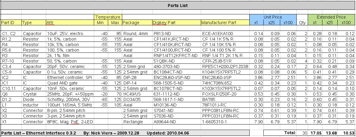
Components:
The parts list that corresponds to schematic version 0.3.2 is shown below. All parts are available from Digikey.com.
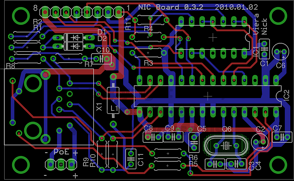
Printed Circuit Boards:
A Printed Circuit Board design for the Ethernet Controller Board has been completed. The PCB is a standard, 2-layer board with through-hole components. It measures 70.1 mm x 43.2 mm. The PCB design layout is shown below, followed by a photo of the PCB populated with components.
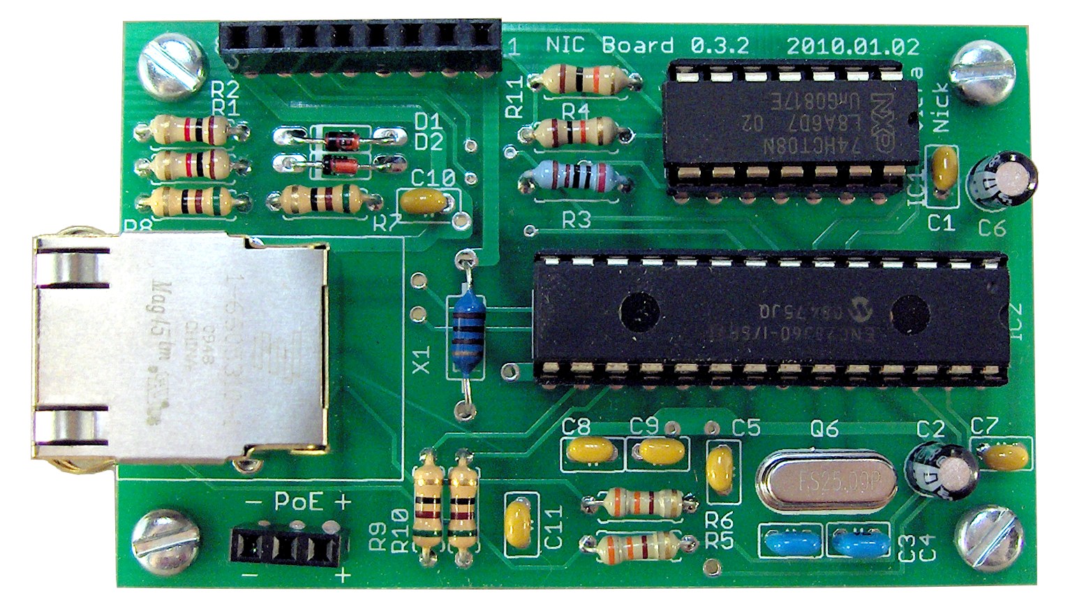
Connections:
The NIC board contains two female pin header connectors, in addition to the modular Ethernet jack. The small, 3-pin header is for the Power Over Ethernet (PoE), and it connects to the PoE input header on the current THAT Power Supply board. The Large, 8-pin header is for data and power for the Ethernet Controller. It is designed to connect to the mainboard of a THAT module.
The 8-pin data header pinout was defined so that the constant power signals (VCC) are near one end, with ground at the opposite end. The data lines then are oriented so that the higher-frequency data lines are close to ground, while the lower-frequency lines are closer to VCC.
The pinout of the 8-pin data header is as follows:
- Pin 1: 3.3 Volts (VCC2)
- Pin 2: 5 Volts (VCC1)
- Pin 3: Interrupt Signal
- Pin 4: Ethernet Chip Select Signal (CS)
- Pin 5: Serial Peripheral Interface Slave Out (MISO)
- Pin 6: Serial Peripheral Interface Slave In (MOSI)
- Pin 7: Serial Peripheral Interface Clock (SCK)
- Pin 8: Ground
Date Added: 2010/04/05 ¦ Modified: 2010/04/05

‹ Copyright ©2009 - 2010 Nick Viera and Chris Miller ›