THAT Home Automation Topology
The Open Home Automation and Control System
« Electronic Access Module »
- Introduction
- THAT Overview
- THAT Hardware
- Digital Thermostat Module
- Electronic Access Module
- THAT Control Software
- Capstone Project Deliverables
Introduction:
The Electronic Access Module (E.A.M. Version 1.0) is an advanced control module for use with THAT. It shares the basic goals and requirements defined for THAT and is designed for use with residential and light-commercial buildings. An additional submodule, called the Door Widget, extends the EAM's functionality by adding a doorbell button and a randomly-rotating passcode interface. Both devices were developed by Chris Miller.
Hardware Specifications:
The EAM makes use of the THAT Power Supply and THAT Network Interface. These components are described in detail in their respective sections above.
The EAM hardware includes an embedded 8-bit microcontroller. The microcontroller is an Atmel AVR Atmega324P.
The Atmel AVR series of microcontrollers were chosen for this design primarily because they are widely available, have excellent support for open-source software, and are easy to use with any desktop operating system (including Linux).
The Atmega324P was selected for this design because it offers a large number of Input/Output (I/O) pins coupled with a large flash memory space. In addition, the Atmega324P is pin-compatible with three other microcontrollers in the AVR series (Atmega164P, Atmega644P, and Atmega1284P) which offer options for more flash memory space. Thus, there is the possibility for easy future upgrades should more memory space be needed.
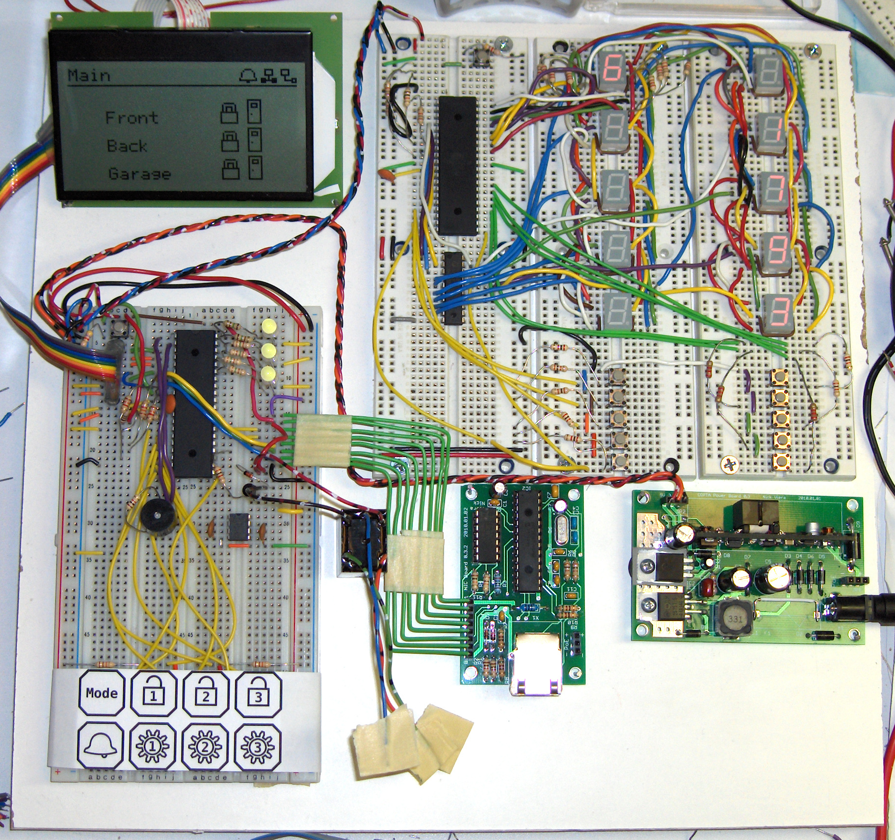
EAM and Door Widget Prototype
User Interface
The EAM's user interface allows for the direct, local interaction between the user and the EAM. The interface components were selected to provide enough feedback and sources of input to make the interface as intuitive as possible. The user interface consists of:
- 3 bi-color LED indicators
- 8 momentary pushbutton switches
- A large, graphical LCD screen with backlight
The LCD is a 128x64 pixel, 3-5/8" screen manufactured by Newhaven Display International. It is monochromatic and has a serial interface. This particular LCD was selected for the EAM mainly due to its relatively large size, increasing its visibility at larger distances.
The Door Widget has a user interface of its own that allows the user to indirectly request access from the EAM. The interface components were selected to allow for intuitive operation. The user interface consists of:
- 10 seven-segment LED displays
- 11 momentary pushbutton switches
- 1 bicolor LED indicator
Seven segment LED displays have several benefits for use in a device such as the Door Widget including their many size options, dimming ability, and flexible spacing options. The particular units used in the Door Widget were chosen due to their wide operating temperature range, high brightness and small size.
Peripheral Communication Interfaces
Two serial communication interfaces are used to transfer data between the microcontroller and peripherals.
A three-wire synchronous serial interface (Serial Peripheral Interface or SPI) is used to communicate with the THAT Network Interface. SPI is used because the Ethernet controller IC on the THAT Network Interface is only available with an SPI bus.
The SPI bus is also used to transmit data to the LCD. The LCD is unidirectional (only capable of receiving data) and therefore uses only two of the three SPI lines.
A two-wire synchronous, I2C-compatible, serial interface is used by the EAM and Door Widget for communication with one another. I2C was chosen for this communication for the following reasons:
- The microcontroller supports I2C in hardware
- Multiple nodes (up to 112) may exist on the same bus
- Distances of over 75ft may be reached with the aid of additional components (bus extender)
- The EAM firmware could be further developed to accept other I2C submodules (such as single doorbell buttons or door-open sensors)
Software Specifications:
The base firmware for the EAM and Door Widget is written in the C programming language. The firmware currently implements the functionality necessary for electronic access through the main user interface of the EAM. Significant progress was made towards working communication between the EAM and Door Widget, as well as the master computer through the EAM's Ethernet / TCP stack. These two portions have been fully-implemented in hardware and partially-implemented software but are still non-functional.
Design Concept:
The EAM was designed with utilitarianism in mind. It could easily be mounted within a metal box in an out-of-the-way location.
The Door Widget, however, was designed to be aesthetically pleasing due to being installed near residential entrances. The physical design concept drawing used during the design process is shown in Figure 1 with important features indicated in Figure 2.
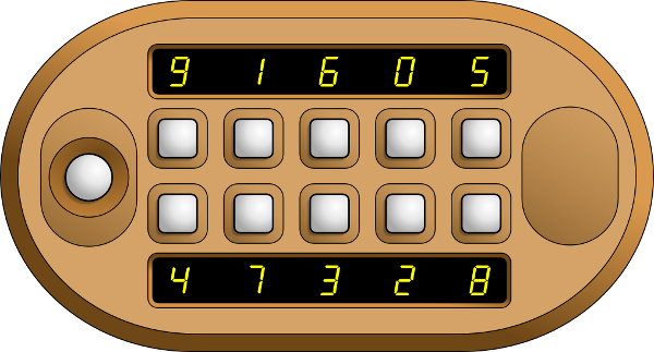
Figure 1: Door Widget Design Concept
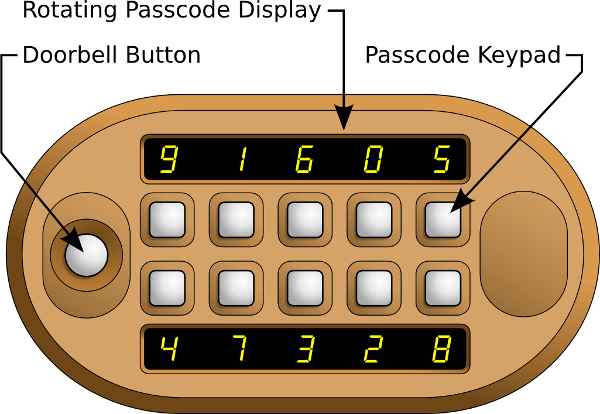
Figure 2: Door Widget Important Features
Block Diagram:
The overall hardware system block diagram for the EAM is shown in Figure 3. The overall hardware system block diagram for the Door Widget is shown in Figure 4.
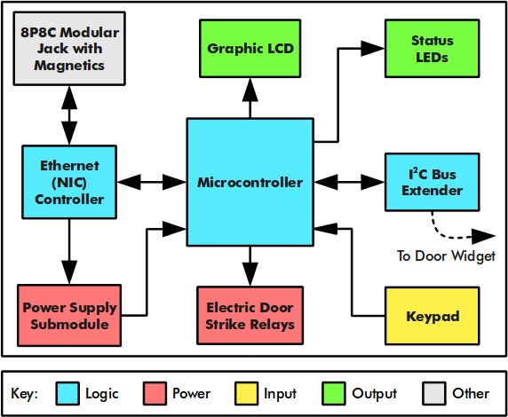
Figure 3: EAM Block Diagram
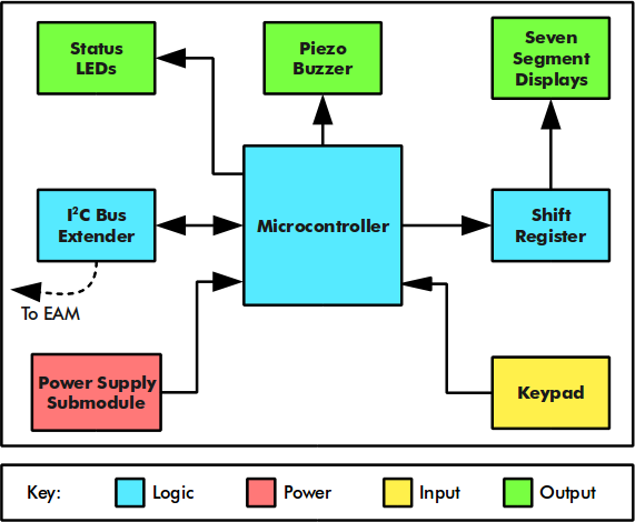
Figure 4: Door Widget Block Diagram
Parts List:
The parts lists for the EAM and Door Widget are shown in Figure 5 and Figure 6 respectively.
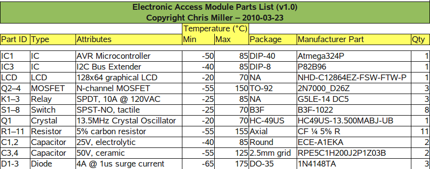
Figure 5: EAM Parts List
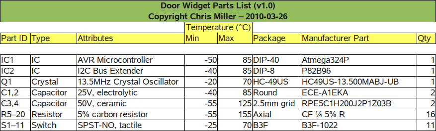
Figure 6: Door Widget Parts List
Schematics:
The schematic for the EAM is a single document that can be found in the next subsection. The schematic for the Door Widget is split up into two parts. The first schematic contains the microcontroller (MCU) portion of the design. The second contains the display portion of the design.
EAM Schematic
The schematic for the EAM is shown in Figure 7. Notes about this schematic are listed below.
- IC1 is the Atmel Atmega324P microcontroller.
- IC2 is the NXP P82B96 I2C bus extender.
- K1 through K3 are relays with a maximum load rating of 10 A at 120 VAC and 8 A at 30 VCD.
- MOSFETs Q1 through Q3 are buffers that allow the relays to be driven without exceeding the current limit per I/O pin of the AVR microcontroller.
- D1 through D3 are flyback diodes to prevent large voltage spikes from appearing across the MOSFETs' drain-source junction when the relay coils are de-energized.

Figure 7: EAM Schematic
Door Widget MCU Schematic
The schematic of the Door Widget's microcontroller portion is shown in Figure 8. Notes about this schematic are listed below.
- IC1 is the Atmel Atmega324P microcontroller.
- IC2 is the NXP P82B96 I2C bus extender.
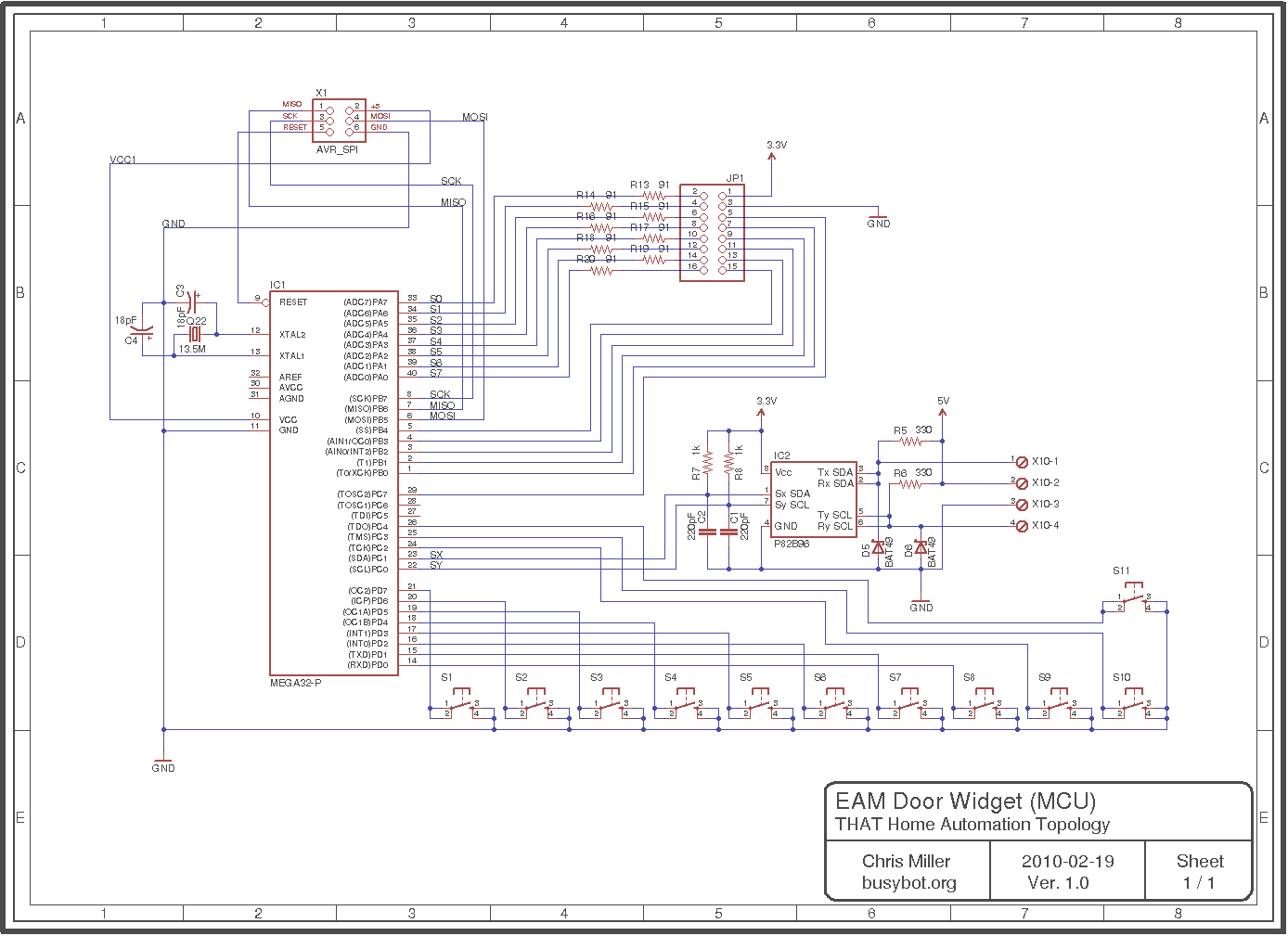
Figure 8: Doow Widget MCU Schematic
Door Widget Display Schematic
The schematic of the Door Widget's display portion is shown in Figure 9.

Figure 9: Doow Widget Display Schematic
Date Added: 2009/09/16 ¦ Modified: 2010/05/14

‹ Copyright ©2009 - 2010 Nick Viera and Chris Miller ›