THAT Home Automation Topology
The Open Home Automation and Control System
« Digital Thermostat Module »
- Introduction
- THAT Overview
- THAT Hardware
- Digital Thermostat Module
- Electronic Access Module
- THAT Control Software
- Capstone Project Deliverables
Overview:
The Digital Thermostat Module (version 1.0), code-named COPTA, is an advanced control module for use with THAT. As such, the COPTA design shares the basic goals and requirements defined for THAT. This module has been developed by Nick Viera. COPTA is a digital thermostat with an advanced feature set and flexible programmable control. It is designed for use with most standardized residential and light-commercial, single or split-unit HVAC systems.
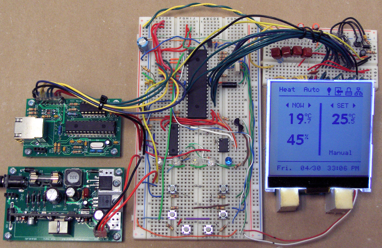
Digital Thermostat Prototype Hardware
Hardware Specifications:
Microcontroller Platform

Hardware Block Diagram
The COPTA hardware consists of an embedded microcontroller system. The microcontroller is an Atmel AVR Atmega324P. The Atmel AVR family of microcontrollers was chosen for this design primarily because they are widely available, have excellent support for open-source software, and are easy to use with the Linux operating system.
The Atmega324P was selected for this design because it offers a large quantity of Input/Output (I/O) pins coupled with a large flash memory space. In addition, the Atmega324P is pin-compatible with 3 other AVR microcontrollers (Atmega164P, Atmega644P, and Atmega1284P) which offer options for more flash memory space. Thus, there is the possibility for easy future upgrades should more memory space be needed.
In addition to the microcontroller, a Microchip MCP23008 I/O port expander is used to provide and additional 8 I/O pins. The use of the port expanded was necessary to ensure that all peripherals and user interface devices could be implemented without running out of I/O pins.
Sensors
COPTA contains an on-board analog temperature sensor and a capacitance-based relative humidity sensor. Both sensors are read by the microcontroller through its integral Analog to Digital converter (ADC). The temperature sensor is a Microchip MCP9700A IC. It reads temperatures in the range of -40 to 125 °C with an accuracy of +/-2 °C across typical indoor air temperatures (0 to 70 °C).
The MCP9700A was selected for this design because it is inexpensive, physically small, and has both the accuracy and measuring ranges desired for this design. In addition, the sensor can operate at either 3.3 or 5 Volts DC and is offered in a through-hole package.
The humidity sensor is a Honeywell HCH-1000 sensor. It measures levels of 10% to 95% Relative Humidity with an accuracy of +/-2 %RH. The HCH-1000 sensor was selected for this design because it is offered in a through-hole package, has an integral case for dust-protection, and is less expensive than other alternatives.
Real Time Clock
For programmability, the thermostat design includes a real time clock (RTC), which keeps time using its own crystal oscillator (for stability and accuracy). The RTC used is the Dallas DS1337+ IC. This IC was selected mainly due to its availability in a small, through-hole package and its I2C data bus.
User Interface
The user interface allows for the direct, local interaction between the user and the thermostat module. The interface components have been selected to provide enough feedback and sources of input to make the interface as intuitive as possible. The user interface consists of:

Prototype LCD readout
- 5 LED indicator lamps (red, amber, green, blue, and white)
- 6 momentary pushbutton switches, laid out as 3 discrete pairs
- A large, graphical LCD screen with backlight
The LCD screen is a 128x128 pixel chip-on-glass device manufactured by Newhaven Display International. It supports 16 shades of gray, and is almost exactly square in shape. This particular LCD was selected for the thermostat module mainly due to its physical size and shape matching the desired traits. A lot of emphasis was placed on finding such an LCD, in order to stay true to the physical design concept (see section 5.4).
Software Specifications
The microcontroller firmware for COPTA is written in C and compiled into AVR assembly code by AVR-GCC. The firmware implements both the functionality necessary for thermostat operation, and the Ethernet / TCP stack necessary for THAT communications. Overall software design goals are listed below:
- Modularity in design.
- Configurable support for single and multi-stage A/C and heat-pump systems.
- Configurable support for controlling dynamically variable HVAC systems.
- Configurable support for reading external temperature/humidity sensors.
Physical Design Concept:
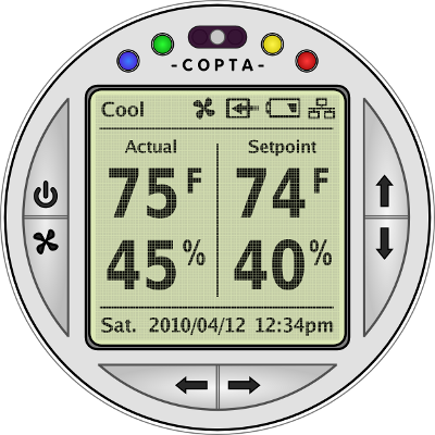
Digital Thermostat Concept Drawing
(Actual size at 72 dots per inch)
The COPTA module is designed to be a stand-alone unit capable of directly replacing any "standard" wall-mount thermostat. To achieve this goal, the unit must not be too large in size and should be as aesthetically pleasing as possible. The physical design concept for COPTA is a unit approximately 115mm in diameter, and 51mm deep.
A brief overview of the user interface elements of the Digital Thermostat Module is shown below. The pushbutton switches all serve multiple functions. Primary functions are shown in black. Secondary functions, such as when in a menu or settings mode, are shown in [Blue]. Finally, functions which are executed when a button is held down for 5+ seconds are shown in (Red).
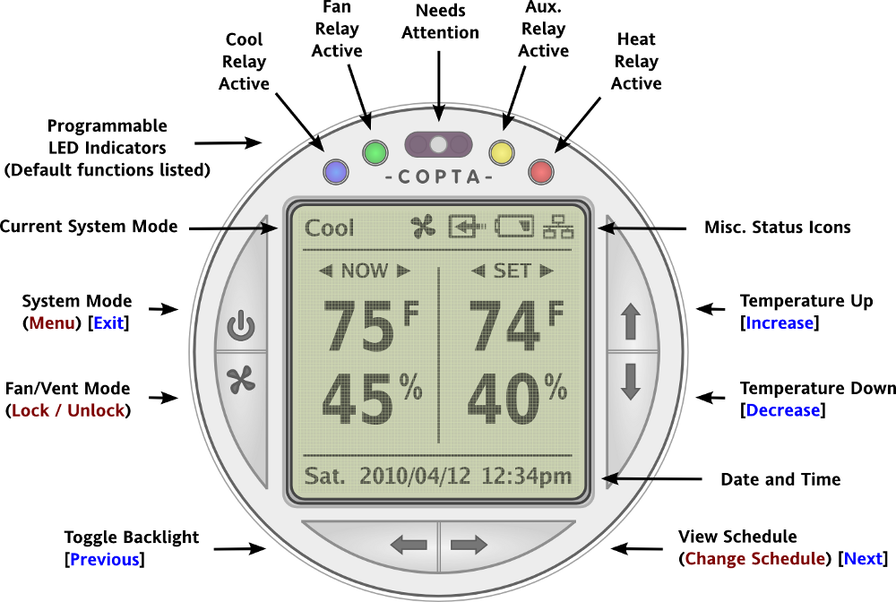
User Interface Key
Schematics:
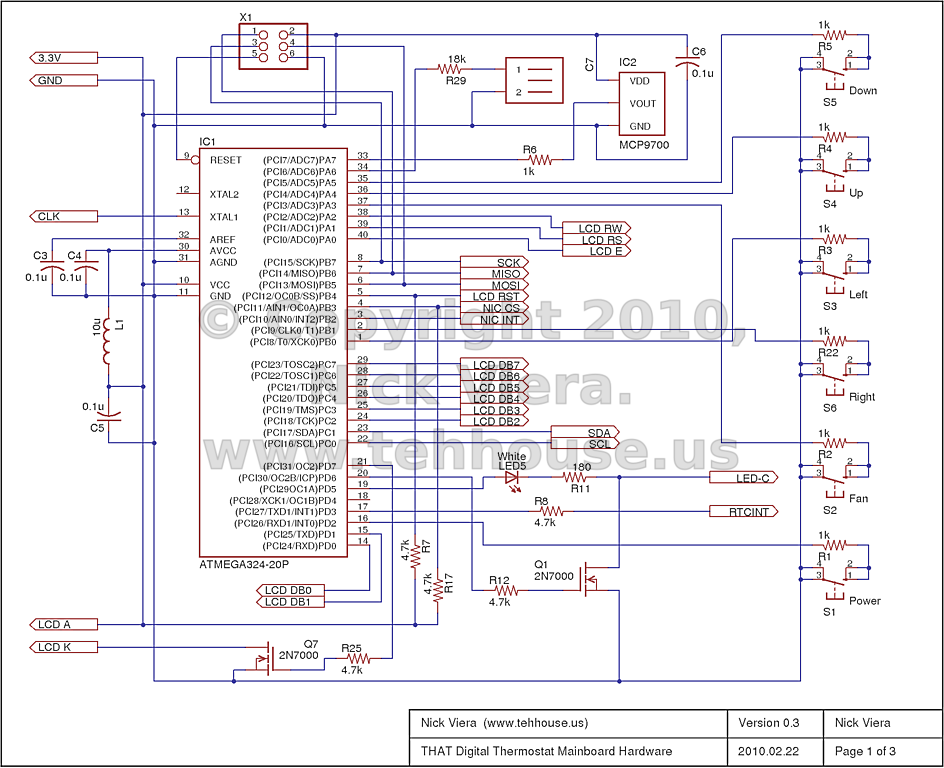
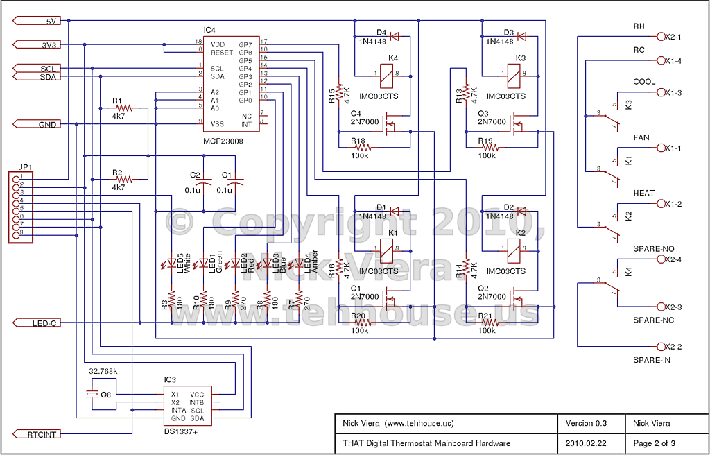
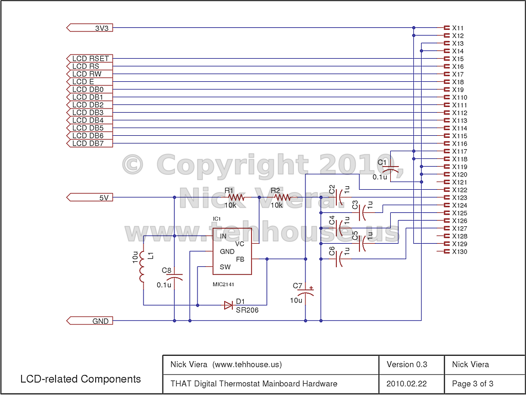
Mainboard Schematic I2C Schematic LCD Schematic
Parts List:
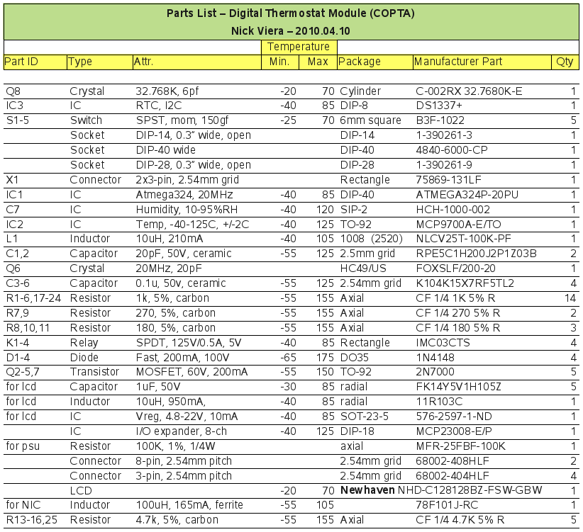
Digital Thermostat Parts List
Date Added: 2009/09/16 ¦ Modified: 2010/05/14

‹ Copyright ©2009 - 2010 Nick Viera and Chris Miller ›