


CFLED Lamp (Version 1)
- A simple, custom-made 120-Volt LED lamp -
")
Compact Fluorescent Lamps (CFL) are an efficient and long-lived lighting source. However, like all lamps, they eventually "burn out" and sometimes fail prematurely. One alternative I thought of to recycling failed lamps is to reuse the parts for custom LED lamps. This page documents version 1 of my simple "CFLED" lamp design.
The Idea
I do a lot of random lighting projects with LEDs. However, I rarely make LED lighting that is powered directly from the AC mains (120-Volt AC), due to the lack of having any inexpensive AND safe enclosures for the circuitry. While I was gathering some old failed CFLs one day with the intention to recycle them, I realized that the body of CFLs (aka the ballast cases) would be about the right size for holding the circuitry needed to make some compact 120-Volt LED lamps.
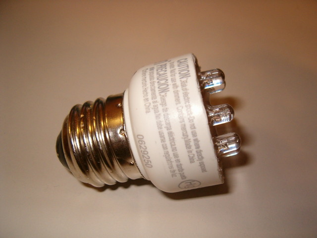
In addition, the CFL bodies are designed to be both fire-retardant and safe for use with AC mains power; thus making them a safer alternative to cheap "project" boxes. Though, the best attribute of reusing a CFL ballast case is that you get the standard edison screw base connector for easy interfacing to most existing light fixtures.
Materials List:
- (1) Old / defective Compact Fluorescent Lamp (CFL)
- (1) 0.47uF, 250V, non-polarized capacitor (like Digikey P/N P10734-ND) **
- (1) 180-ohm, 1/2-Watt metal film resistor (like Digikey P/N PPC180W-1CT-ND)
- (1) 1-Meg ohm, 1/4-Watt resistor *
- (1) Bi-directional TVS Diode (Optional) *
- (4) 1N4004 or similar (400V, 1A) Diodes
- (7) "Super-bright" T 1-3/4, 5mm diameter LEDs
- A small piece of perf. board
- Some short lengths of small-diameter wire (i.e. 24 or 28 AWG)
- Hot glue, electrical tape
NOTES:
* The 1-Meg ohm resistor must be placed directly in parallel with capacitor C1 for safety reasons!
* These components are discussed in detail in the update section.
** The capacitor should be a film-type capacitor rated for AC mains use!
** For 220 to 240 Volts AC mains power, use a 0.22uF, 600V capacitor for C1.
Step 1: Disassemble the CFL
In order to reuse the CFL's ballast case, the case needs to be separated from the fluorescent tube (which is usually a spiral shape. Most CFLs are constructed with a joint line between the bottom of the fluorescent tube and the top of the ballast case. This joint between the two plastic parts of the case is usually epoxied together, so the best way to separate it is to cut through the seam.
I've found that the best way to open this joint is to use a hacksaw to cut all the way around the CFL until the plastic seam is completely cut open**. Once the seam is open, the fluorescent tube will only be connected to the ballast case by 2 or 4 very thin, uninsulated wires. These wires can easily be cut with a knife or wire cutters**. See My TCP EDO-9 CFL teardown page for more photos of the teardown process.
** USE CAUTION WHEN HANDLING THE CFL to ensure that you don't shatter or crack the fluorescent tube. Most fluorescent tubes contain trace amounts of mercury and must be recycled or otherwise disposed of properly!!!
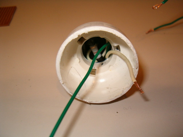
After you've separated the ballast case from the fluorescent tube, you can usually remove the ballast from the ballast case by gently prying up one corner of the printed circuit board. The ballast board will be connected to the edison screw base connector by two short wires. The goal is to cut these wires as close as possible to the circuit board, so the ballast can be removed but also so that as much of the wire remains in the empty ballast case as possible.


The CFL is split open at the ballast case - tube joint
and the ballast is pryed out from the ballast case.
Step 2: Build a simple power supply
Since LEDs are low-current devices, they generally cannot be directly powered from 120-Volt (mains) power without a power supply or current-limiter of some sort. For the design of this compact LED lamp, I opted to use a simple RC circuit and bridge rectifier as a buffer between the LEDs and the mains power. The simple circuit behaves like a current-limited power source for the LEDs, and I chose it due to it's extreme simplicity. Below is the schematic of this circuit and a SPICE simulation of it's input and output behavior.
This circuit relies on capacitive energy transfer, and thus only works correctly from AC power at 50-60Hz. The resistor limits the peak inrush current to a safe value for the LEDs, while the bridge rectifier diodes allow power to be delivered to the LEDs during both the positive and negative half-cycles of the AC waveform. Thus, the LEDs shine with a nice, relatively constant light (unlike many LED christmas light sets which produce a very noticeable flashing/"strobing" effect due to the lack of a full bridge rectifier).


Schematic and SPICE simulations of the simple AC-DC power supply.
Note: Green traces show potential (Volts), blue traces show current (milliAmps).
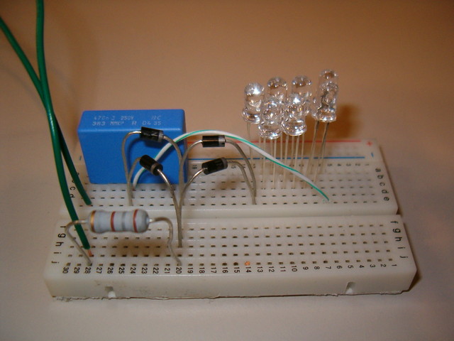
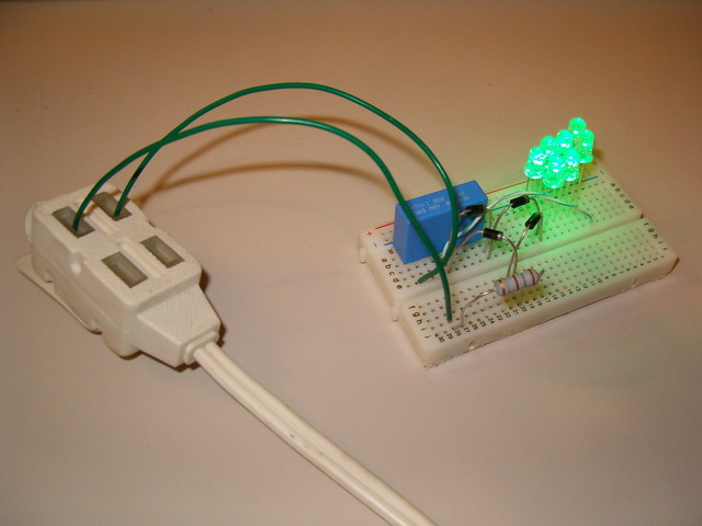
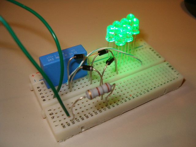
I built the power supply circuit on solderless "breadboard" and tested its real world performace with 7 green LEDs connected to it; while powered from the AC mains power. The simple power supply works well, producing about 30mA peak, which is about the maximum continuous forward current for the "super bright" green LEDs I chose to use. By the way, use breadboards as shown at YOUR OWN RISK with AC mains voltages! They are NOT designed or rated for use with high-voltages like used in this project! With that said, I've experienced no problems using them with AC mains voltages for short durations of time.


I built and tested the power supply on solderless breadboard.
Step 3: Install the power supply
With the power supply tested, I turned my attention to stuffing the components into the base/ ballast case of the old CFL. At first I was worried that there wasn't enough space, but I discoved that if I installed the 180-ohm, 0.5-Watt resistor down into the screw base, the 0.47uF, 250-Volt capacitor and four (4) 1N4004 diodes fit nicely above it; all while leaving plenty of room for a board of LEDs above. This process is best shown through photos, which are below. Basically, the resistor and capacitor are installed into the base first, with the diodes being installed (and glued into place) afterwards. Since the diodes need to connect to both the capacitor and resistor (per the schematic), I used short jumper wires to make these connections easier. All connections were soldered and covered with electrical tape as needed to prevent shorting between wires.


The power supply is connected, soldered, and installed into the old CFL base.
Hot glue was used to secure the components to the plastic walls of the lamp base.
Step 4: Install the LEDs
The last step was to solder up and install the LEDs above the power supply. The LEDs I chose ended up being very good for this application because they are "super-bright" (about 5000-7000mcd) and have an excellent viewing angle (45 degrees). So they put out a excellent amount of light for use as a decorative spot-light, night light, etc...
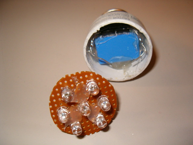
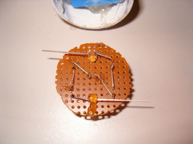
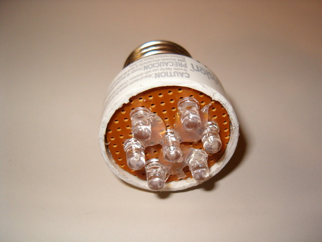
Since I had seven (7) LEDs to install, I decided to try and space them evenly around the board, which I cut into a circular shape from some scrap perforated circuit board material. The LEDs are all wired in series, and the positive and negative ends of the LED string were connected to the positive and negative outputs from the power supply diodes, respectively (per the schematic above). Once the connections were all soldered, I pushed the circular board containing the LEDs down into the old CFL ballast case. Luckily, the board snapped firmly into the case, so there was no need for me to glue it in place. Well there you have it... an incredibly simple, inexpensive way to make small, efficient, 120-volt AC, LED lamps for decoration, amusement, night light use, etc...


The LEDs are soldered onto a circular piece of perforated board.
then the board is connected and installed into the lamp base.
Further Considerations
Power Source: This CFLED lamp is designed for use only with 110 to 120 Volts AC, 50 or 60Hz mains power. It can optionally be modified for operation from 220 to 240 Volts AC, 50 or 60 Hz as noted in the materials list section. Usage of this lamp design with any other power source (including dimmer switches) is not tested and NOT recommended!
Number of LEDs: The design of the CFLED's power supply allows for the quantity of LEDs to be changed to suit the application. The capactitor-resistor power supply is essentially a constant-current power source capable of delivering about 30mA peak to the LEDs. Increasing or decreasing the number of LEDs in the series-connected string will not change the amount of current provided by the power supply nor the amount of current required for illumination of the LEDs. Instead, only the voltage required to drive the LEDs will increase or decrease.
As long as the total voltage required to light the LEDs is below about 1/2 the minimum voltage provided by the AC mains power, the LEDs will light at full brightness. Therefore, a 120 Volt AC mains supply should be able light up to at least 20 LEDs connected in series (using the components listed above.) The number of LEDs that can be lit from a 240 Volt AC mains supply will be about double that.
Important Update
This page discusses the original CFLED (version 1). Since the first authoring of this page in 2009, I have made several changes to the CFLED design, which are discussed below. More information about the latest version of my CFLED design (version 2) is available from Sicada at http://www.sicada.com/products/
The latest version of my CFLED design contains two new components which make the design more robust (see the updated CFLED version 2 schematic below). The 1-Meg ohm resistor R2 is new and is placed in parallel directly across the capacitor C1. This resistor is not mandatory but is HIGHLY recommended. It ensures that the capacitor gets discharged whenever the CFLED is turned off, to remove any possible shock hazard from lingering charge.
The other new component is the TVS diode D11. This diode is placed in parallel with the entire LED string. It is a high-power, bi-directional diode which helps protect the LEDs from any power surges. It should be selected so as to have a conducting voltage just above the max voltage across the LED string. For a 10 LED string, a 36-Volt TVS diode is ideal. For a 5-LED string, an 18-Volt TVS diode is ideal.
")
The updated schematic for CFLED version 2, showing new components.
|
CFLED Lamp (version 1) Photos |
|||
 Large || XL |
 Large || XL |
 Large || XL |
 Large || XL |
 Large || XL |
 Large || XL |
 Large || XL |
 Large || XL |
 Large || XL |
 Large || XL |
 Large || XL |
 Large || XL |
 Large || XL |
 Large || XL |
 Large || XL |
 Large || XL |
 Large || XL |
 Large || XL |
 Large || XL |
|
