


COBRA MCU
- Servo Motor Control Interface -
COBRA MCU is a simple, microcontroller-based signal interface/ converter. It reads up to six (6) channels of servo-motor control signals and converts them into standard Pulse Width Modulation (PWM) signals as well as 0-5 Volt DC analog signals. It is a useful interface for robotics and Radio-controlled (RC) applications.
Purpose:
The "COBRA MCU" Interface was designed and built by myself with the help of Chris Miller beginning in February of 2009. We are members of the Competition-Oriented Bradley Robotics Alliance (COBRA) at Bradley University; the student robotics club. At the time COBRA was designing its 120lb (54kg) robot, named Jail Break, for the 2009 BattleBots Competition.
Radio control of the robot consisted of a "standard" 2.4GHz hobby / RC radio transmitter and receiver system. The standard output from RC radio receivers are multiple "servo motor control signals", which are PWM signals whose duty cycles are limited within a narrow range. The specific "on" times of these PWM signals correspond linearly to the range of motion of a servo motor, usually between 0 and 180 degrees or -90 to +90 degrees of rotation.

PWM versus Servo Motor Control Signal
In most cases, having these servo motor control signals is no problem because you are either driving actual servo motors or motor speed controllers who can accept this type of input to control the speed and direction of "normal" (non-servo) motors. Since the Jail Break robot was so heavy, COBRA decided to use large DC motors with motor speed controllers designed for scooters, golf carts, forklifts, mini-EVs, etc... Well of course these motor speed controllers were NOT designed to accept servo motor control signals. Instead they accept a 0 or 5 Volt logic signal to select motor direction, and a 0 to 5 Volt analog signal to set the motor speed.
Therefore the COBRA MCU Interface was designed to be a converter between servo motor control signals and the 0-5 Volt signals required by the motor speed controllers. We knew this was a task that could be easily handled with a basic 8-bit microcontroller and some C code, so we set out build the interface.
Specifications:
- Inputs:
- Six servo motor control signal inputs
- Inputs are standard 5V logic compatible
- Outputs:
- Four 0 to 5V analog outputs
- Two (active high) digital outputs (for driving 5V logic)
- One (active low) open-drain digital output (for driving a relay coil)
- Seven output/status LEDs
- Power Requirements:
- Voltage: 7-20V DC input
- Current: Approx. 90mA maximum at 7V
- Connectors (including modifications):
- 2-pin, 2.54mm pitch female pin header for bringing VCC and Ground onto the board.
- 2-pin, 2.54mm pitch female pin header for providing power to the radio receiver.
- 7-pin, 2.54mm pitch female pin header for RX and BIND Inputs from the radio receiver.
- 7-pin, 2.54mm pitch female pin header for the Analog and Digital Logic Outputs from the microcontroller
- 9-pin DB-9 male connector also used to carry the Analog and Digital outputs from the microcontroller. The pinout used for the DB-9 connector is as follows:
- Pin 1: Ground
- Pin 2: Right speed signal (Analog)
- Pin 3: Right brake signal (Analog)
- Pin 4: Right reverse signal
- Pin 5: Weapon relay coil control
- Pin 6: Left speed signal (Analog)
- Pin 7: Left brake signal (Analog)
- Pin 8: Left reverse signal
- Pin 9: Main relay coil control
Schematics:
The schematics for the COBRA MCU Interface are shown below. Due mainly to the short turn-around time, the schematic and PCBs were subsequently modified during and after the battlebots competition we competed in to fix errors and improve reliability. The newest schematic is shown first, with the older versions below.


Old COBRA MCU Schematics, version 1.3 (left) and 1.2 (right). Version 1.3 reflects PCB version 1.1 after
some modifications, and version 1.2 matches PCB version 1.1 as it was manufactured in April 2009.
The microcontroller is programmed to output Pulse Width Modulation (PWM) signals on Pins 11,12,15,16. The resistors R2,R3,R4,R11 and capacitors C4,C5,C6,C7 are used to form a low-pass filter with a cutoff frequency much below the frequency of the PWM (which is about 10kHz). In this way, the resistors and capacitors are used to effectively convert the PWM signal to a 0-5V analog signal. If capacitors C4-C7 are omitted, then the PWM signals will appear at the "Speed" and "Brake" output pins instead of an analog voltage.
PCBs:
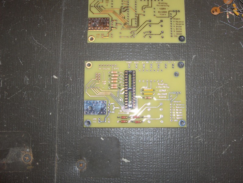
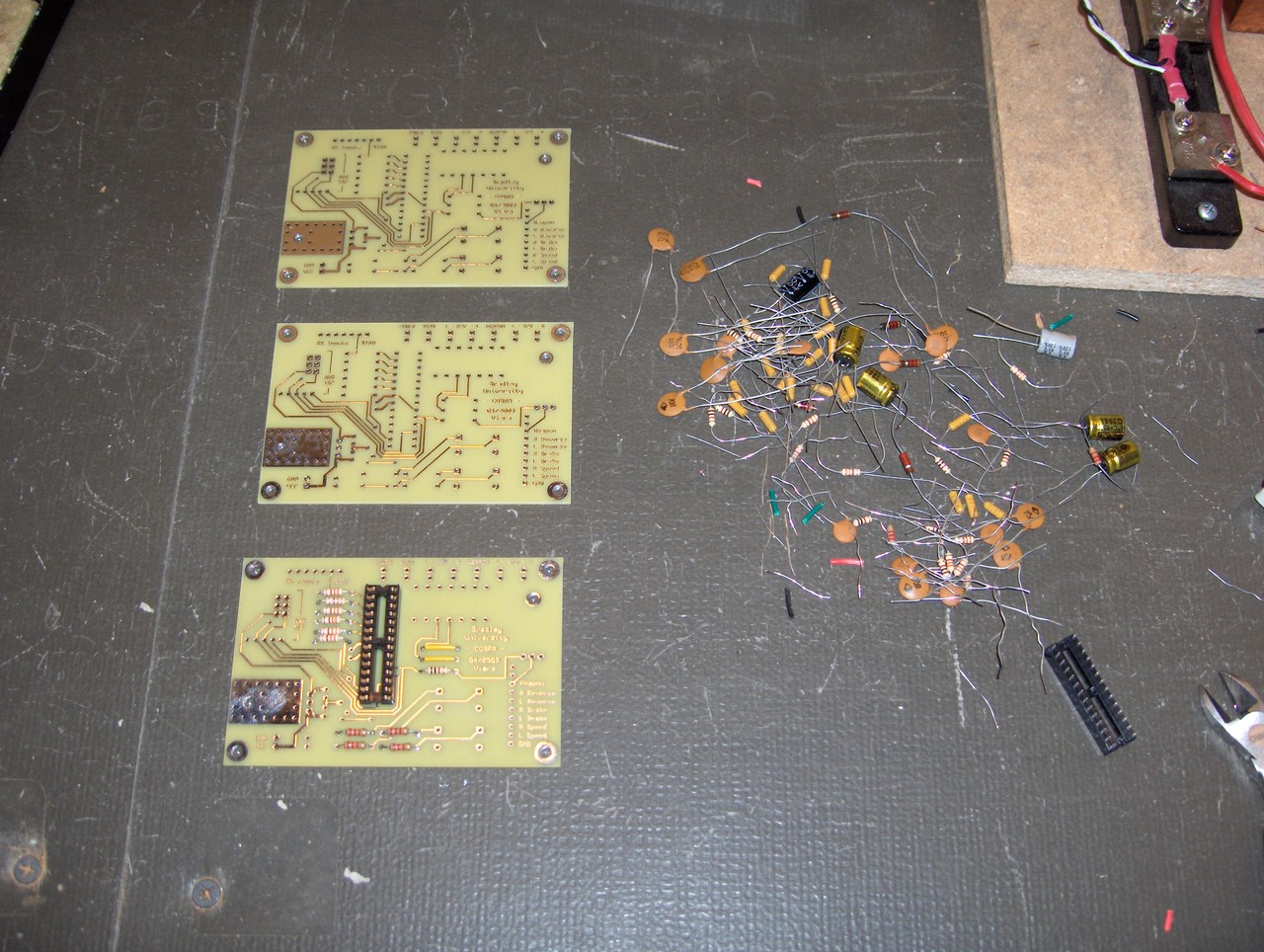
The PCBs for COBRA MCU are shown below. Version 1.1 is the newest, and was created using ExpressPCB software from http://www.expresspcb.com. The boards are standard, 2-layer copper boards with outer dimensions of 3.8" x 2.5" (96.52mm x 63.5mm).


COBRA MCU PCB layout, (unmodified) version 1.1. Download the ExpressPCB layout file here.
PCB v1.1 Errata / Suggested Improvements:
- The drill holes for the "RX Inputs / BIND" pin header are barely large enough and should be enlarged.
- The drill holes for the main output pads are barely large enough and should be enlarged.
- The two pads directly above the main output pads should ideally be routed to VCC and Ground, respectively. They are currently not connected to any signals.
- There should be a resistor between the BIND input (Microcontroller Pin 28) and Ground. About 750 ohms will work.
- The MOSFET on the board should have a flyback (TVS or Zener) diode connected across it's drain and source. This is necessary to protect it from large voltage spikes if it is switching the coil of a relay.
Firmware:
The firmware we wrote for COBRA MCU is C code that we compiled using the tools included with AVR-GCC and AVR-LIBC. It was created for use on the Atmel AVR ATmega48/88/168/328 microcontroller family, runnning with an 8 MHz system clock. The latest firmware can be downloaded using the links below:
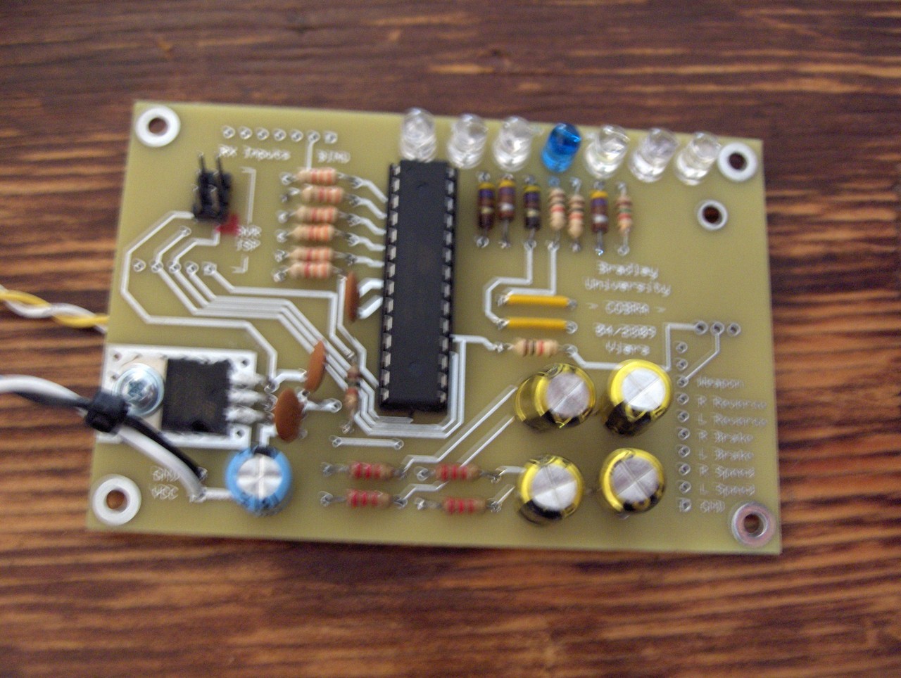
Photos:
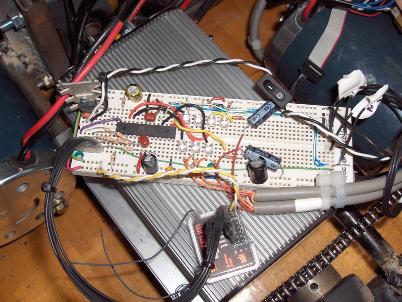
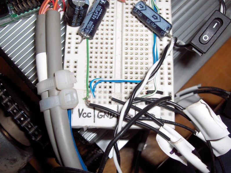
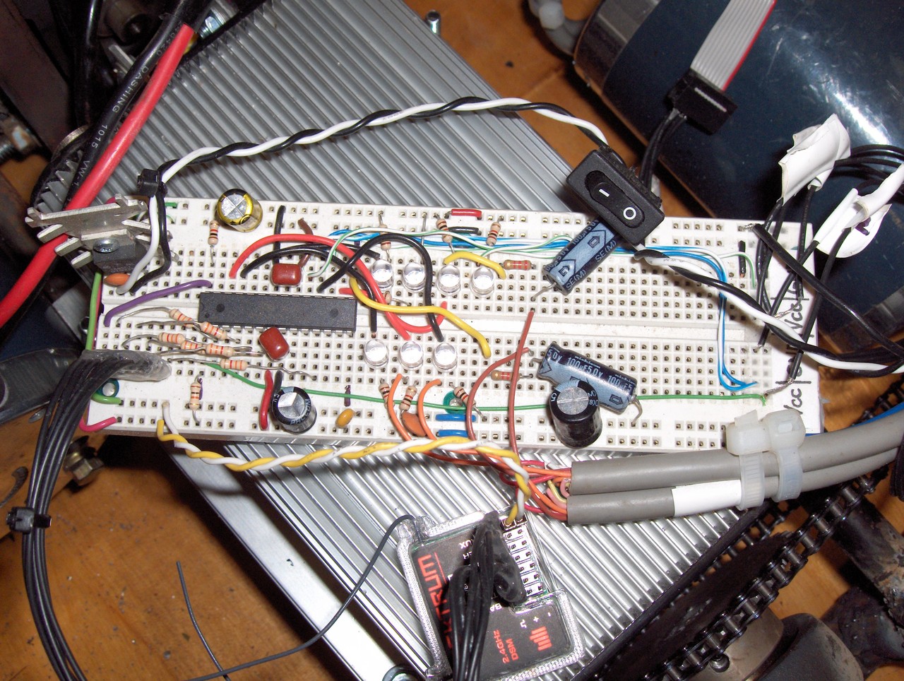
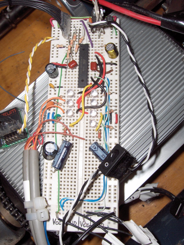
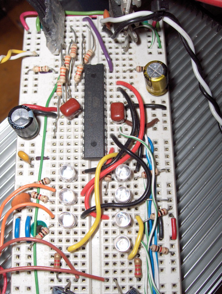
Initial Protoype Photos |
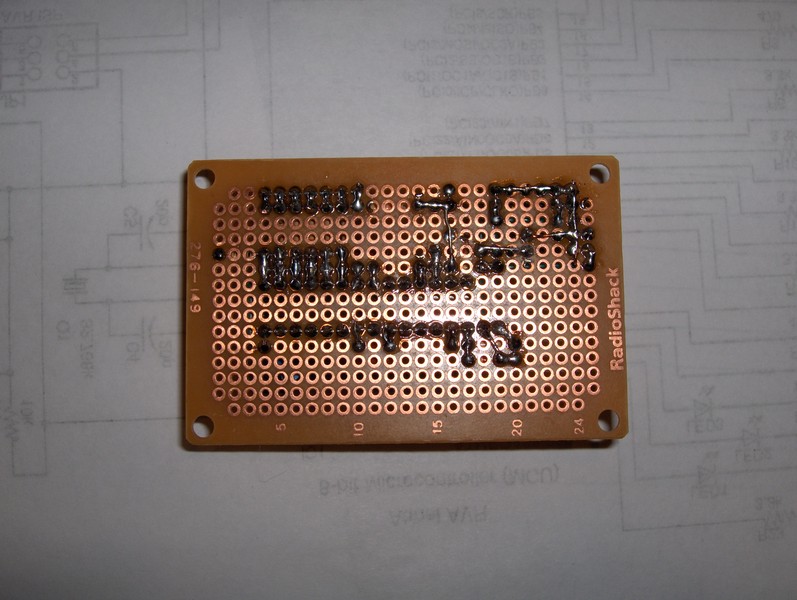
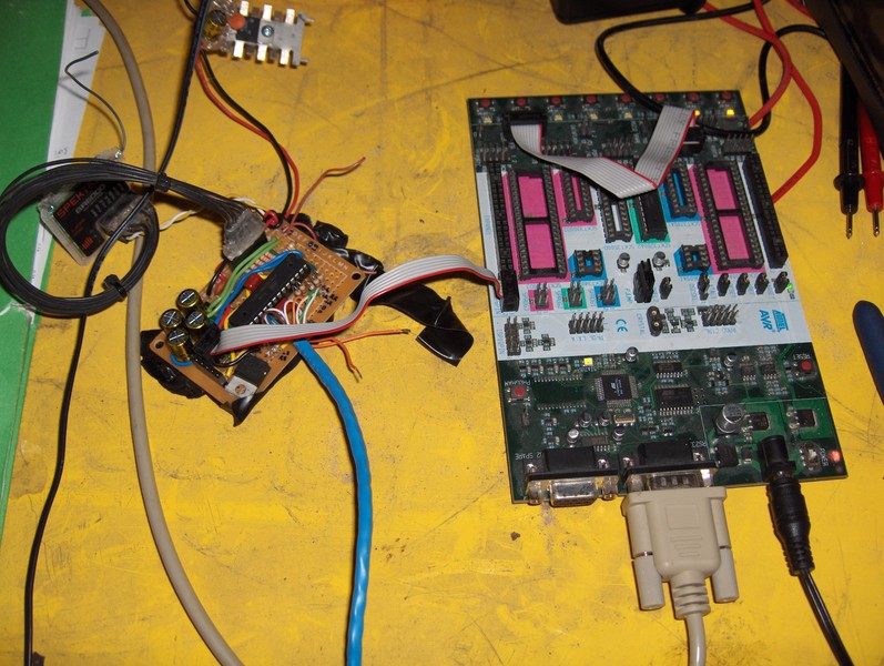
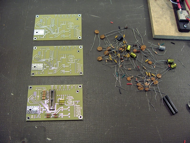
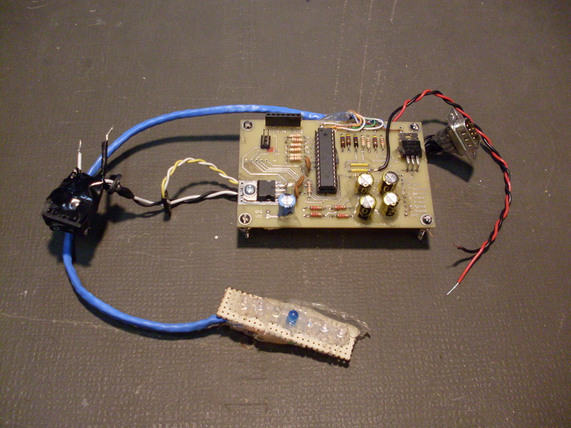
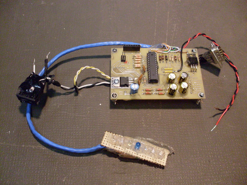
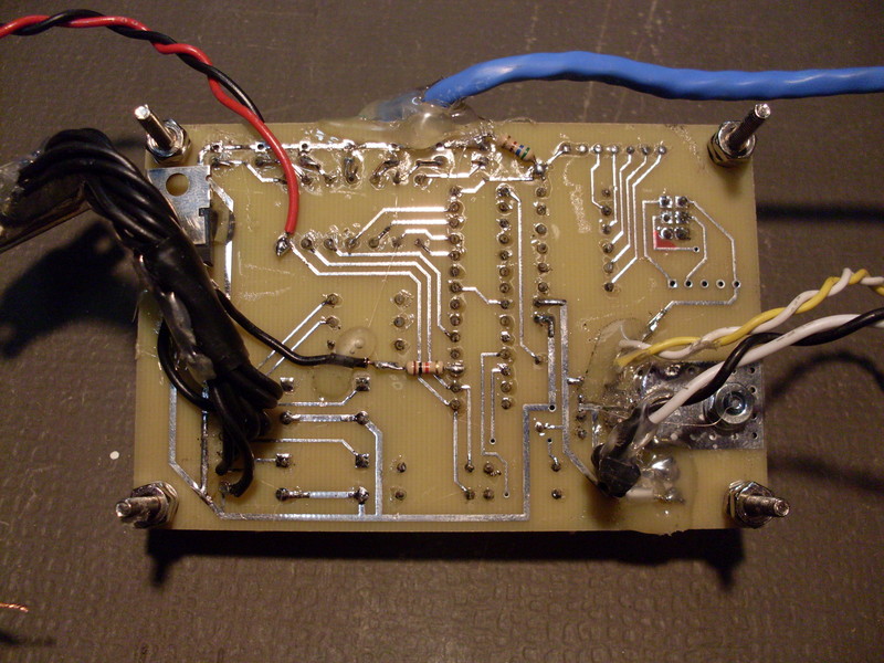
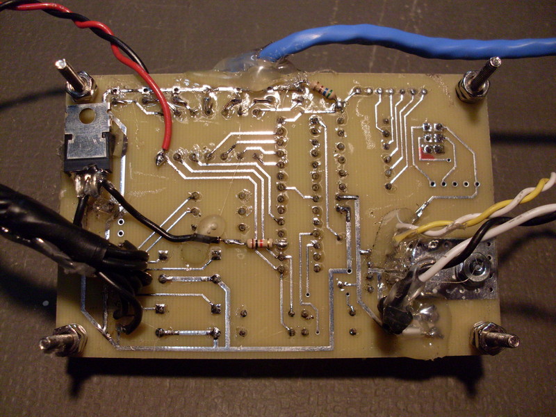
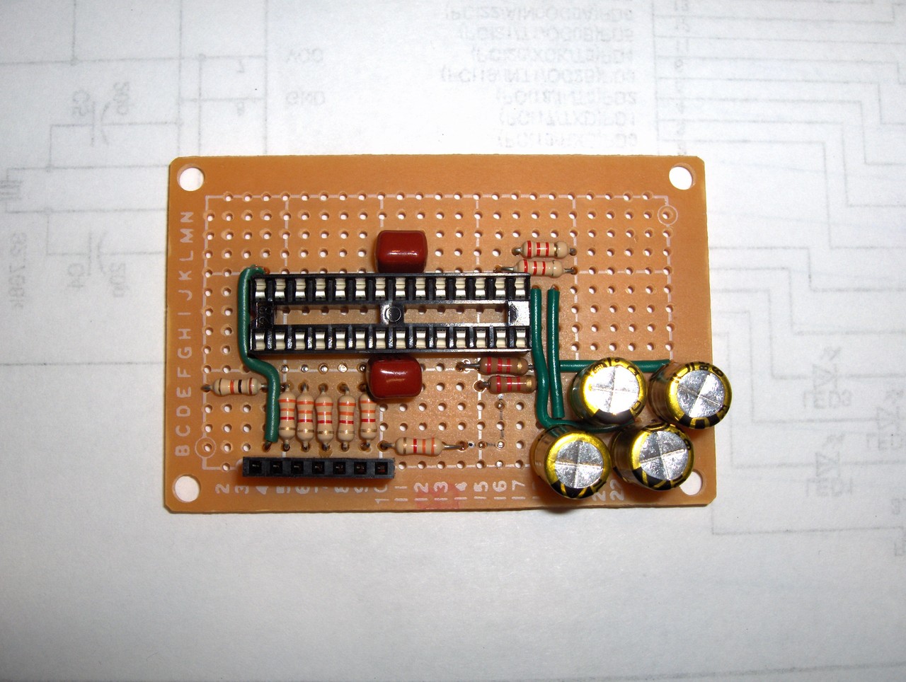
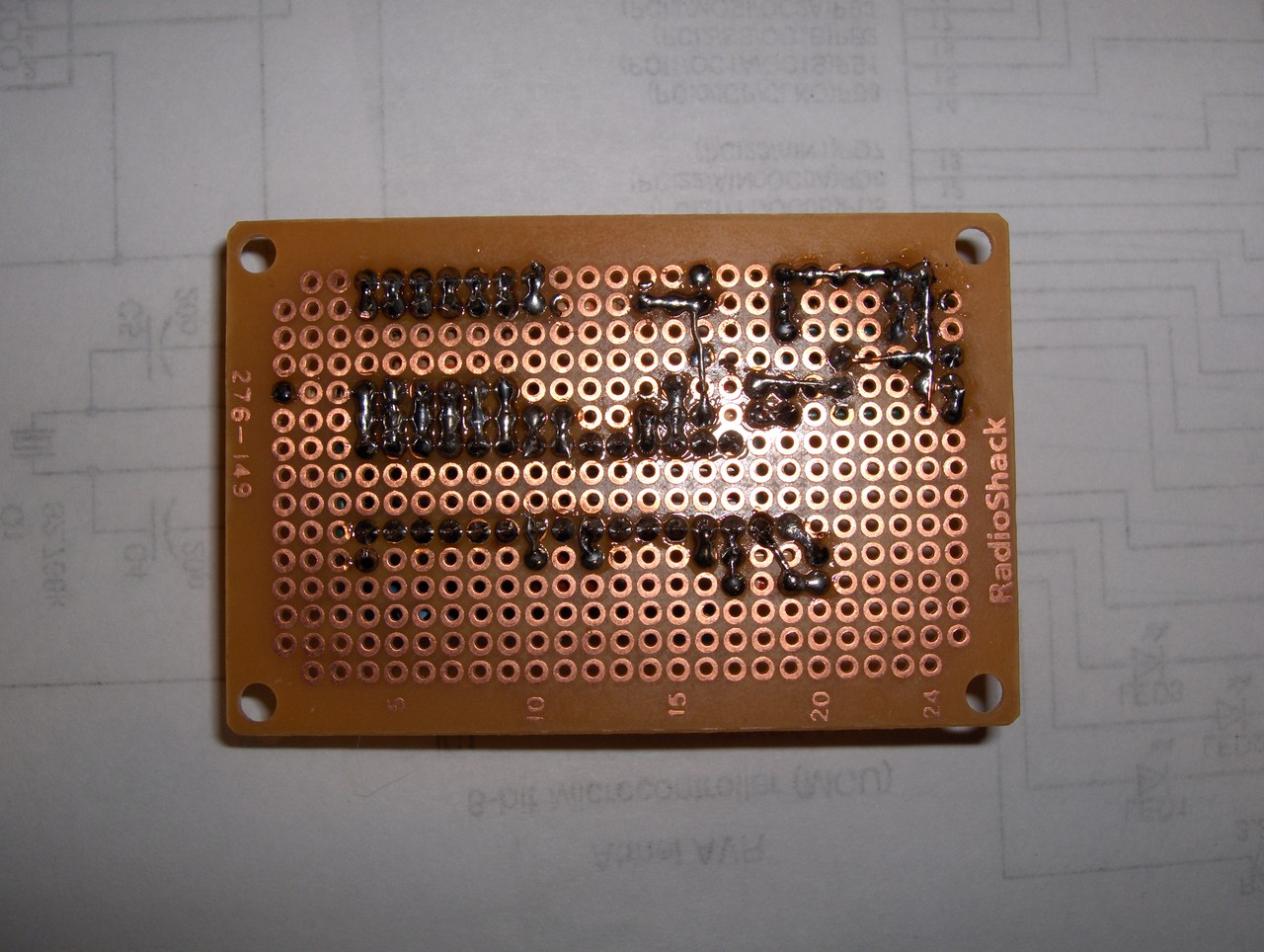
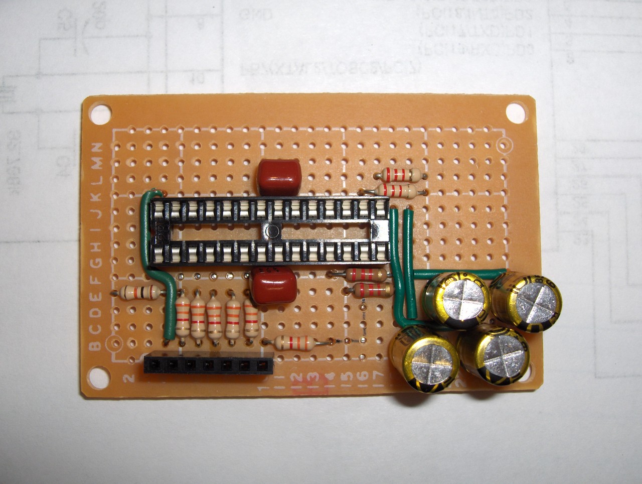
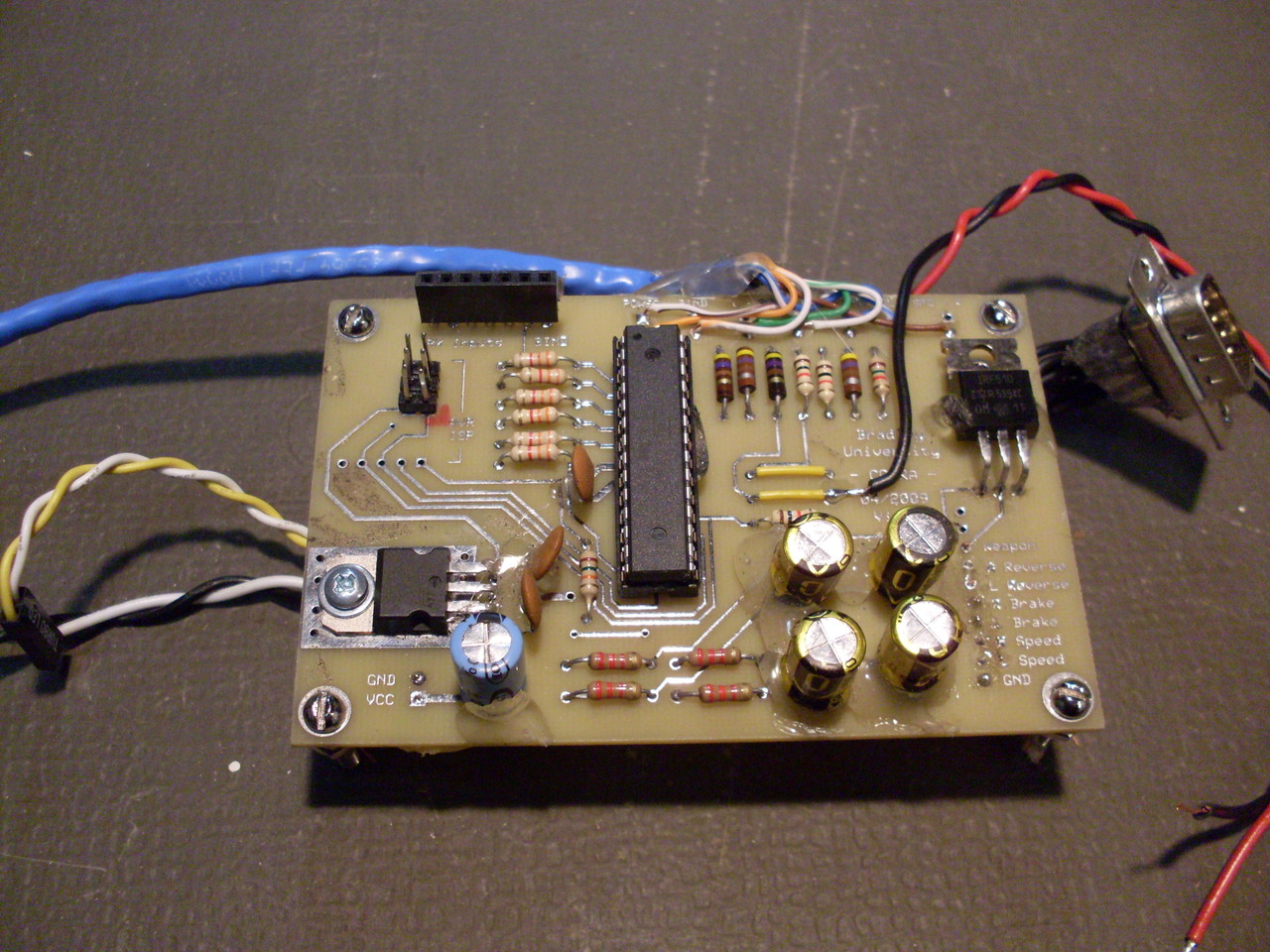
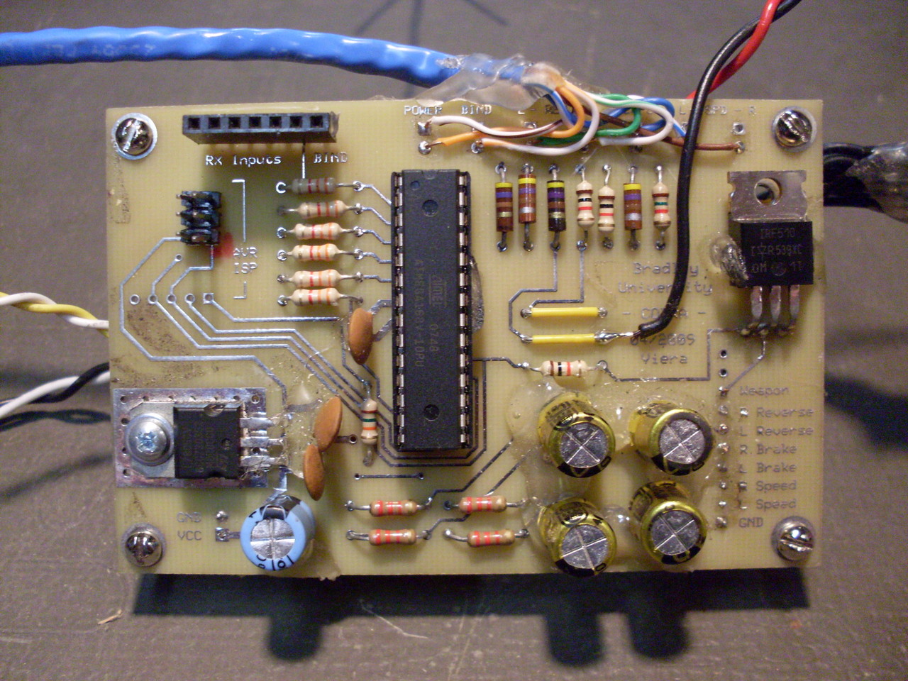
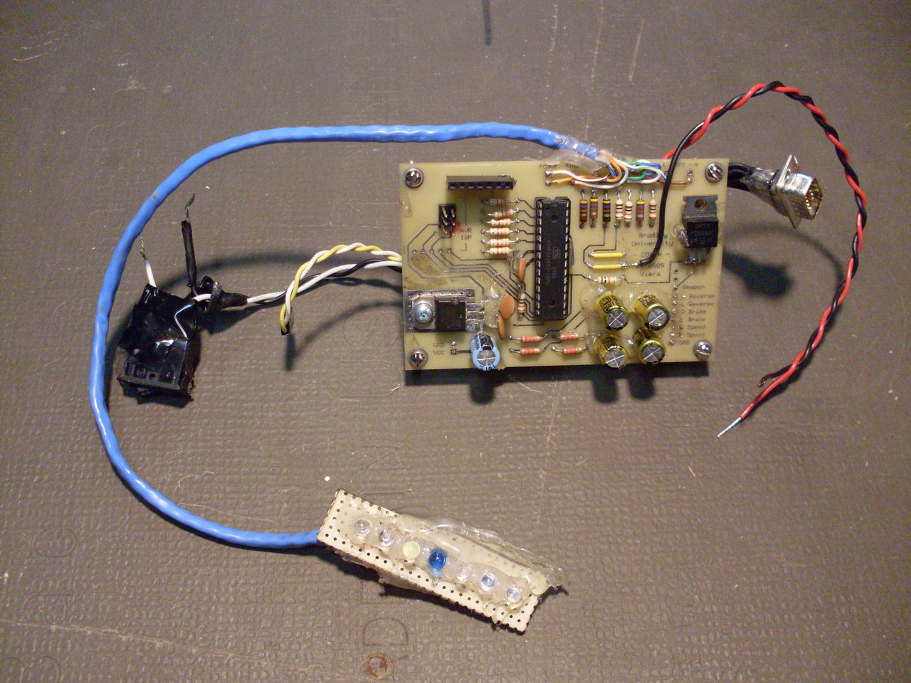
Perf. Board Prototype Photos |
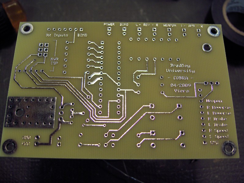
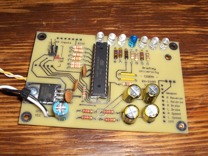
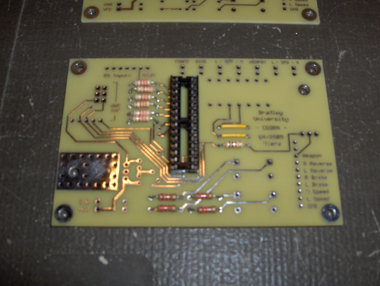
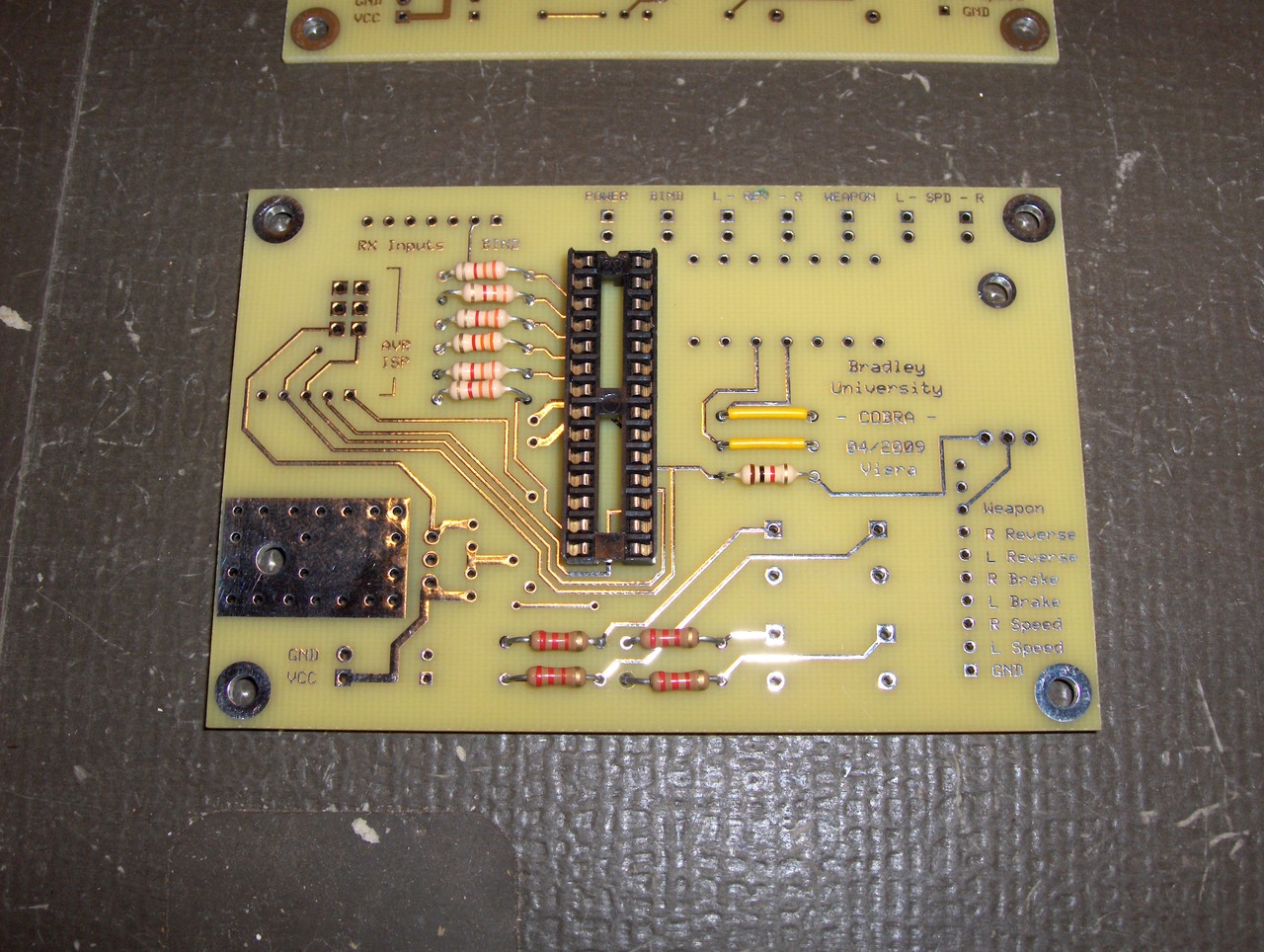
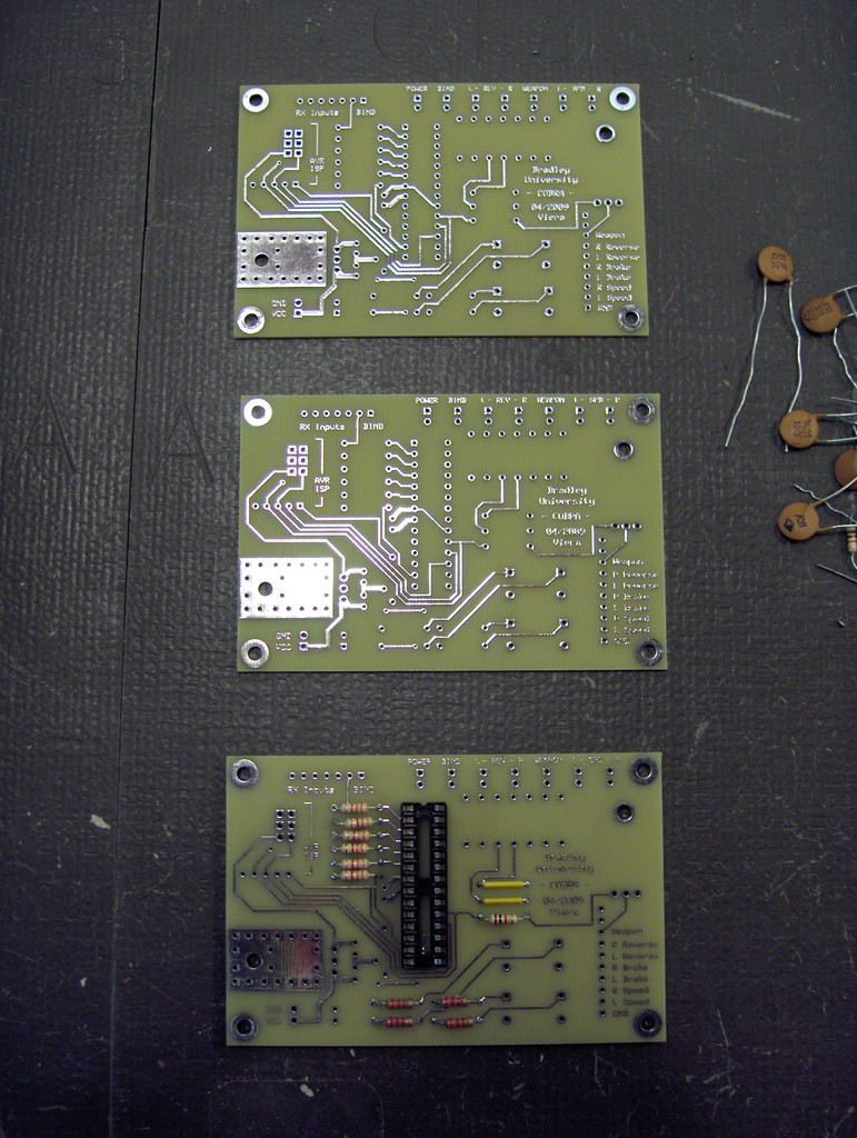
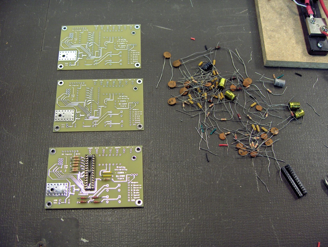
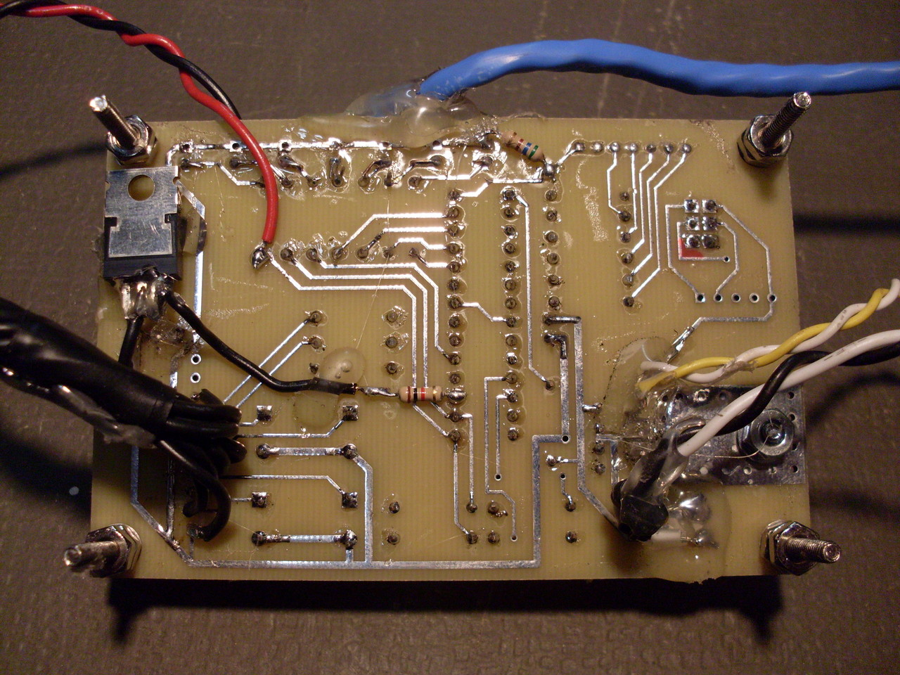
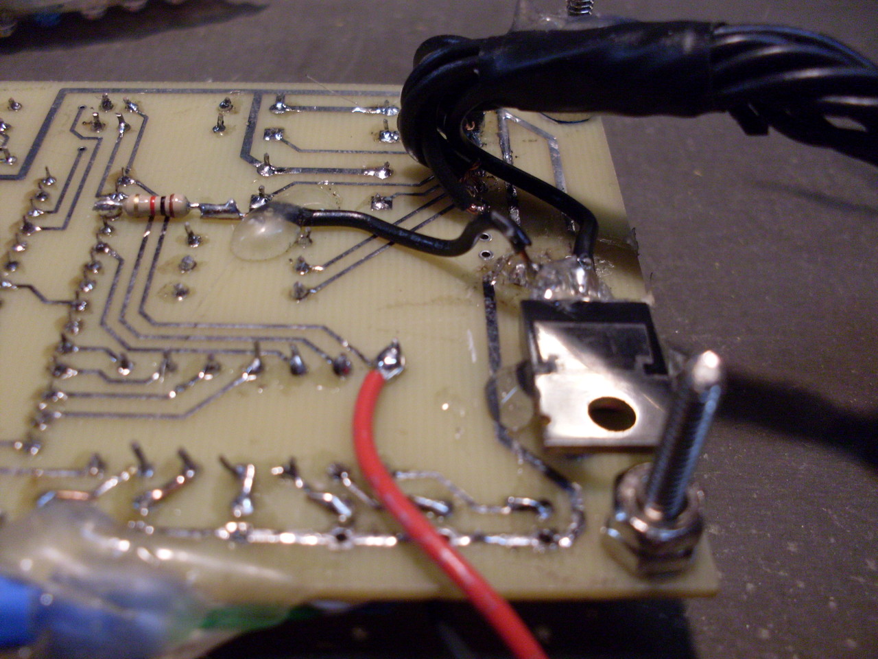
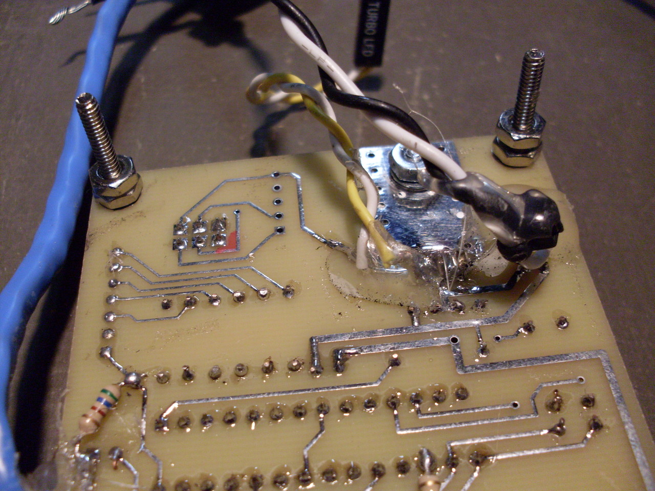
PCB version 1.1 Photos
|
COBRA MCU Initial Prototype Photos |
|||
 Large || XL |
 Large || XL |
 Large || XL |
 Large || XL |
 Large || XL |
 Large || XL |
||
|
COBRA MCU Perf. Board Prototype Photos |
|||
 Large || XL |
 Large || XL |
 Large || XL |
 Large || XL |
 Large || XL |
 Large || XL |
||
|
COBRA MCU PCB version 1.1 Photos |
|||
 Large || XL |
 Large || XL |
 Large || XL |
 Large || XL |
 Large || XL |
 Large || XL |
 Large || XL |
 Large || XL |
 Large || XL |
 Large || XL |
 Large || XL |
 Large || XL |
 Large || XL |
 Large || XL |
 Large || XL |
 Large || XL |
 Large || XL |
 Large || XL |
 Large || XL |
|
Licensing Information:
 The COPTA MCU schematics, firmware, and printed circuit board layouts are licensed by Nick Viera under the Creative Commons Attribution-Share Alike 3.0 United States License. To view a copy of this license, visit http://creativecommons.org/licenses/by-sa/3.0/us/ or send a letter to Creative Commons, 171 Second Street, Suite 300, San Francisco, California, 94105, USA.
