


Simple Traffic Light Controller
- Three Channel Analog Sequencer -

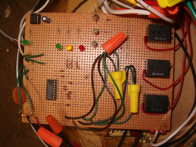
I dug up this old traffic light controller that I built. I consider this simple controller to be the first complete electronics project I ever built (circa 2001). The controller is entirely hardware based, and provides the typical sequencing for a standard 3-light traffic signal.
Introduction:
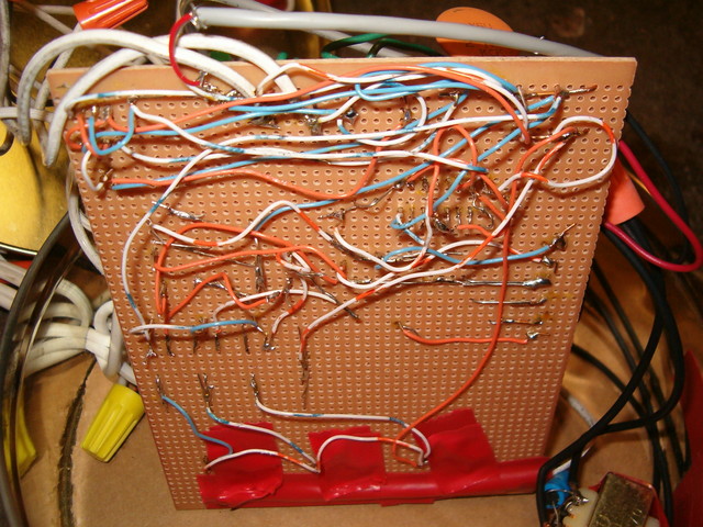
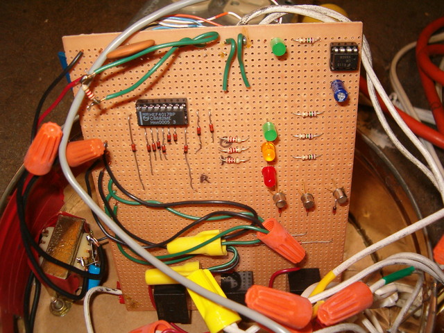
I built this traffic light controller / sequencer when I was first learning electronics, and it is what I would consider a crude and ugly device. However, I learned a lot while building it, and it served its intended purpose... making the traffic signal I bought off eBay flash in the standard Green - Yellow - Red sequence. In addition, I built the controller with variable speed control, and the ability to "hold" any of the lamps full-on or full-off.
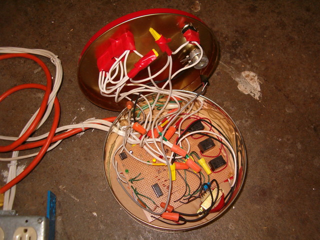
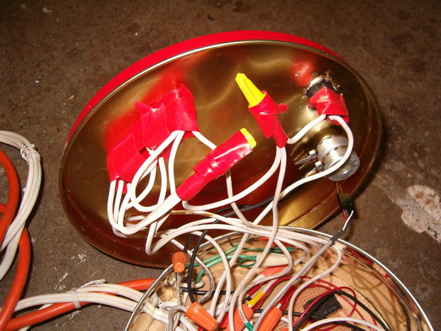
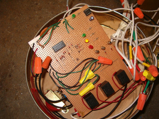
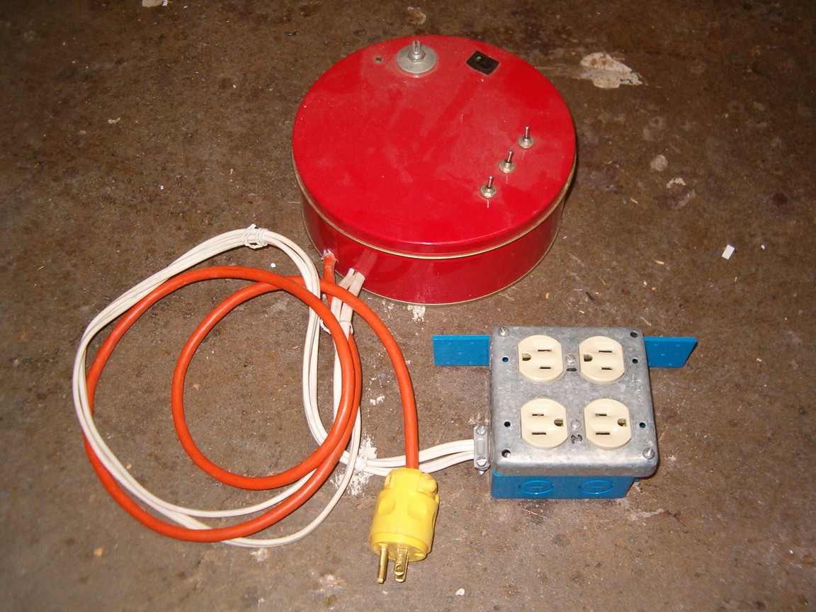
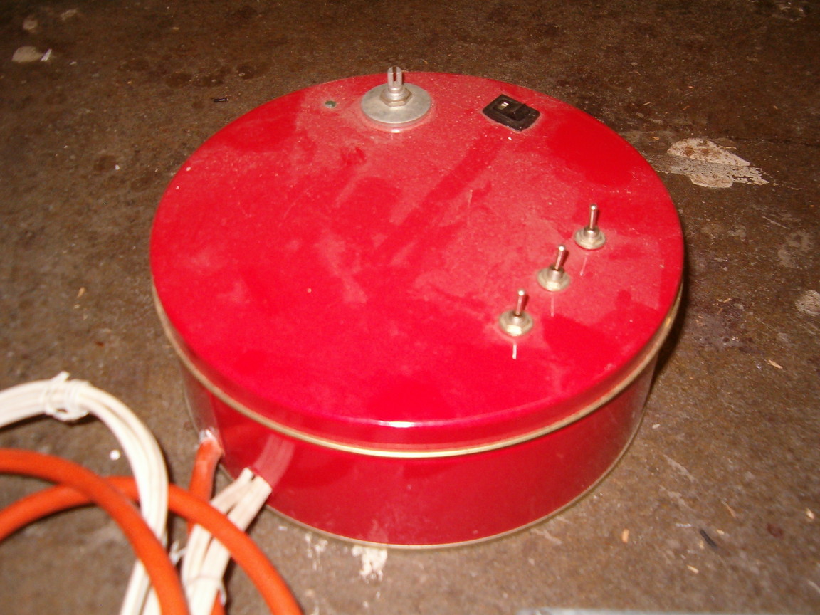
The casing for the controller electronics is an old, re-used cookie tin. While not the most eloquent container; the cookie tin served its purpose while provided my circuit a unique and fire-resistant case. If I were to rebuild this traffic light controller, I would suggest the use of a different casing material.
Materials List:
- Control Components:
- (16) Diodes, 1N4148 or similar
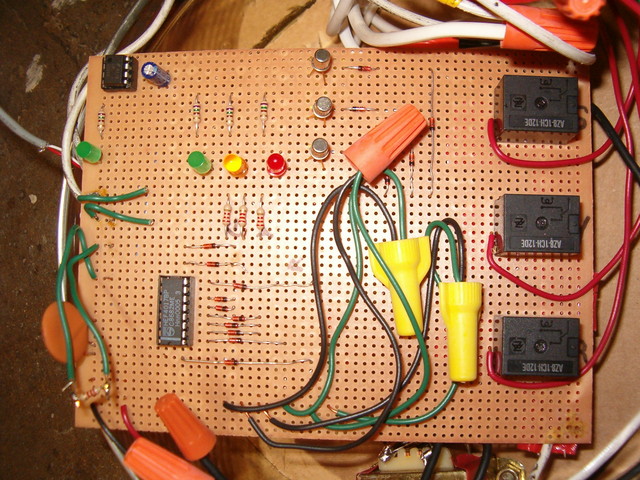
- (5) LEDs, 5mm, Red, Amber, and Green
- (4) Resistors, 750-ohm, 1/4-watt
- (3) Transistors, 2N2222A BJTs
- (3) Resistors, 2.2k-ohm, 1/4-watt
- (2) Capacitors, 0.1uF, 25V ceramic or film
- Capacitor, 10uF, 25V, electrolytic
- Potentiometer, 100k-ohm
- IC, LM555 Timer
- IC, 4017 Decade counter
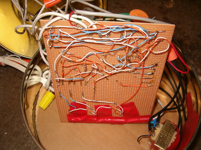
- Perforated Board, Large
- Power Components:
- (3) Switches, Toggle, 120VAC, >= 2-Amp, SPDT w/ center off
- (3) Relays, AZ8-1CH-12DE (Contacts: 120VAC, Coil: 12VDC)
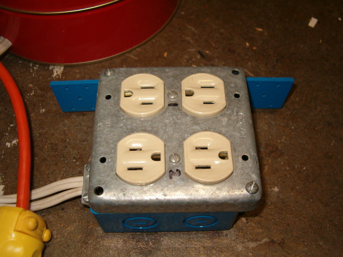
- (2) Receptacles, NEMA 5-15 standard duplex recep.
- Transformer kit, 120VAC to 12VDC (includes a bridge rectifier and bulk capacitor)
- Switch, Rocker, 120VAC, >= 6-Amp, SPST
- Electrical Box, 4" square, dual-gang, plastic
- Electrical face plate, 4" square, 2x duplex cutout
- Wiring, Wire nuts, electrical tape, etc...
Theory:
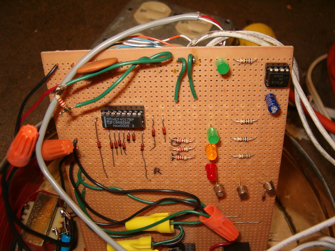
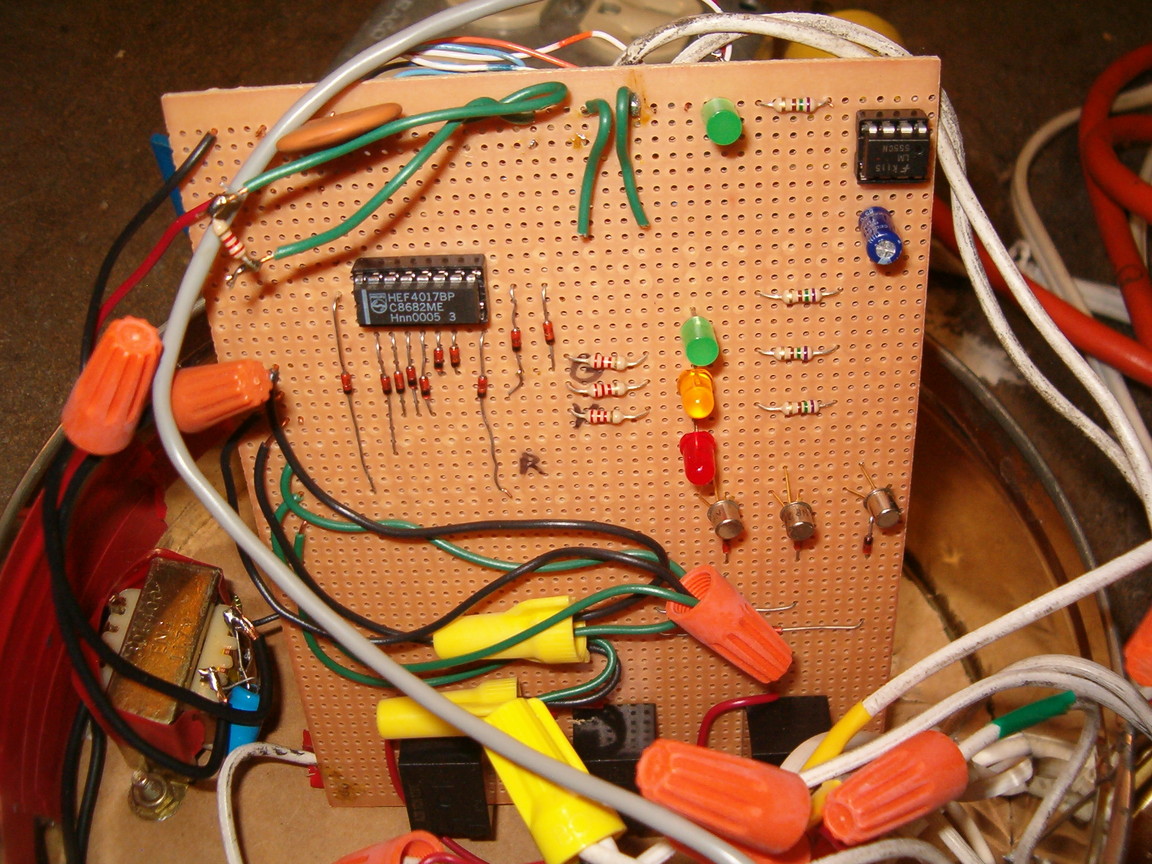
The basic sequencing operation of this traffic light controller is simple. The 555 Timer IC generates a voltage "pulse" at a specific timing interval. This interval is set using a capacitor and two resistors, one of which is the potentiometer (basically a variable resistor).
The 4017 decade counter IC has 10 output ports, of which only one port is turned on at any given time. Each time the 555 Timer sends out a pulse, the 4017 decade counter turns off the currently-active output port, and turns on the next output port. Output port #10 is connected to the RESET pin of the counter, so that anytime the counter tries to activate output #10 it ends up immediately jumping back to Output port #1 (i.e. it starts over counting from 1). In this way the counter loops continuously from output port #1 through #9.
Each of the decade counter's output ports is assigned to a different color light of the traffic signal. For example, mine is connected so that output ports #1 to #4 control the red light, #5 controls the yellow light, and #6 to #9 control the green light. This means that the red and green lights are turned on four times as long as the yellow light is. The multiple outputs for the red and green lights are grouped together using diodes so that power doesn't back-feed into ports on the counter which are currently off.
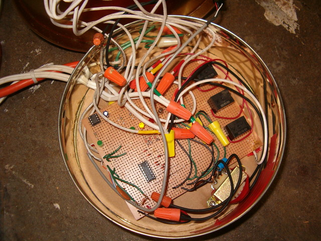
The collective red, yellow, and green outputs from the 4017 decade counter are each connected to a BJT. The BJTs essentially amplify the signal from the decade counter so that there is enough current to drive the coils of the mechanical relays. Thus each BJT's output is connected to its respective relay coil's input.
The relays turn on and off the AC mains power to the traffic light lamps based on the control signal they "see" from the BJTs. In this way they act as "buffers" between the low-power control signals and the high-power 120-Volts AC used to power the lamps in the traffic signal. These mechanical relays also provide electrical isolation between the low and high-power systems in the controller.
Schematic:
The schematic for the simple traffic light controller is shown below.

NOTE: This schematic very closely reflects the actual design of my simple traffic light controller, but has been modified to include several changes which increase the safety of this design. Mainly, the "override" switches for each output are inserted into the low-voltage control signals for the relays instead of directly switching 120-Volts AC, as they did in the original design.
The bold lines in the schematic represent the 120-Volt AC wiring. Extra care should be used to ensure this wiring is well-insulated. Remember, 120-Volt line power can be lethal... proceed with caution!!!
|
Simple Traffic Light Controller Photos |
|||
 Large || XL |
 Large || XL |
 Large || XL |
 Large || XL |
 Large || XL |
 Large || XL |
 Large || XL |
 Large || XL |
 Large || XL |
 Large || XL |
 Large || XL |
 Large || XL |
 Large || XL |
 Large || XL |
||
