


IRcu Infrared Sensor Bar Kit
- A modular replacement for the Nintendo® Wii™ Sensor Bar -
| Introduction | Schematics | Components | PCB Layout |
The idea behind this project is to create a replacement "sensor bar" for use with the Nintendo® Wii™ gaming system and Wiiremotes. The "sensor bar" actually contains no sensors at all, but instead contains two infrared light sources. The Wiiremote's camera "sees" these two infrared light sources, and uses their relative locations to triangulate the position of the wiiremote. In this way the wiiremote can determine how far away it is from the sensor bar, and at what angle it is looking at the bar from.
Unfortunately, the stock sensor bar is not well optimized for many of the installations it is used in. This is caused by the fact that the sensor bar is not adjustable, other than by the user moving it closer to or farther from the TV screen. The result? Often jittery or "low-resolution" response of the wiiremote's cursor on the screen, or intermitten total loss or jumping of the cursor due to the wiiremote loosing track of the infrared sources.
IRcu is the design for a higher-powered, fully modular replacement for the stock sensor bar. Instead of being a single "bar," IRcu consists of identical modules which can be daisy-chained together. By using two or more IRcu modules, you can emulate the stock sensor bar, but with the full flexibility to change the distance between the infrared sources and their distance from you. This allows for much better wiimote operation when you are using the system with a really large TV screen (i.e. projector), a really small screen (i.e. computer monitor), or are standing excessively close to, or far away from, the screen.
In addition, IRcu modules allow the user to adjust the intensity of each Infrared light source, again to allow better calibration for your application. The IRcu modules are powered from 5 Volts DC through standard USB "A" connectors, and contain a USB feedthrough port so they can be daisy-chained.
Schematics:
Below is the latest schematics for the IRcu modules. The eagle schematic and the model schematic used to simulate the circuit in LTspice are shown below. Maximum current through each string of three (3) LEDs is limited to about 20mA, with a 60mA limit overall. The variable resistor R3 (VR1) allows the current to be reduced to control the amount of IR output. When R3 is about 0 ohms, the IR LEDs will be completely off. When R3 is about 1k ohms, the LEDs will be completely on (full power).
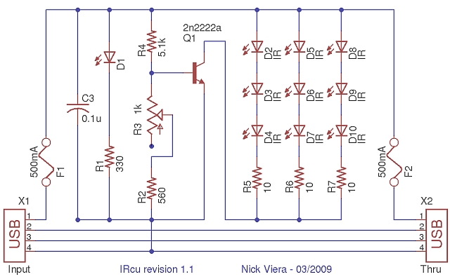
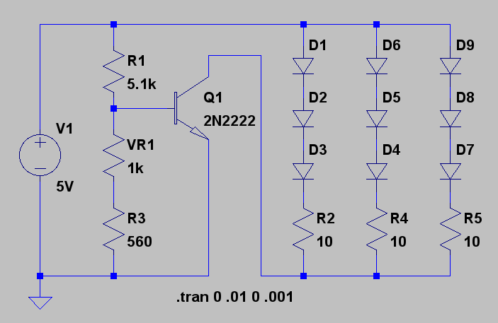
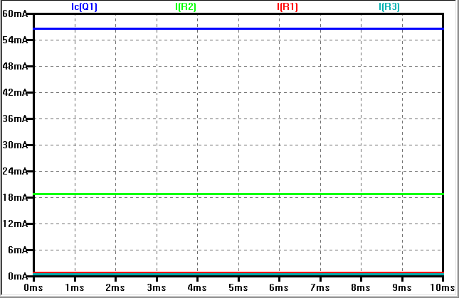
IRcu Schematic revision 1.1 and LTspice model schematic and simulation output.
Components:
The following is a list of the components needed to build IRcu version 1.1. Note that most of the components can safely be substituted with similar parts, but the transistor bias resistors, R2 and R4 should be the values listed. Using lower tolerance resistors (such as 1%) would be best. Also, all part quantities are to build a single IRcu module... ideally you'll want to double the part quantities and build a set of two modules.
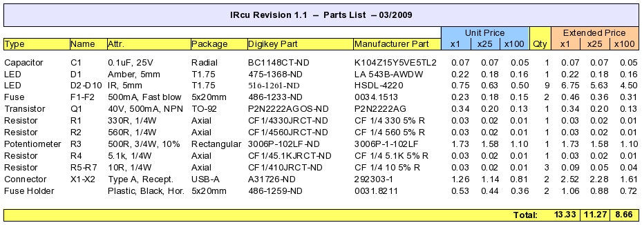
Parts list for IRcu revision 1.1
PCB Layout:
Below is the layout for Printed Circuit Boards for the IRcu modules. The PCB should be a standard, 2-layer PCB with optional solder mask and silkscreen layers. Red represents the top copper layer and Blue is the bottom copper layer for the PCBs. Gray represents the silkscreen layer, which is purely cosmetic, and may be omitted to lower cost. Green areas are the solder pads (solder mask goes in all non-green areas). The final board size is 3.95 by 1.75 inches. The complete PCB layouts in Eagle and Gerber file formats can be obtained by downloading the archive file ircu_1.1_pcb.tar.gz
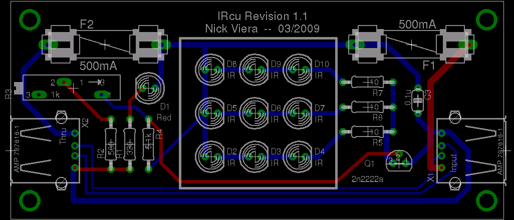
IRcu PCB (All layers shown) revision 1.1
