


Electric Lawn Mower Switch Repair
- Read the Disclaimer! -
See the main Electric Lawn Mower Wiring page for more information
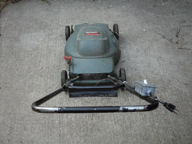
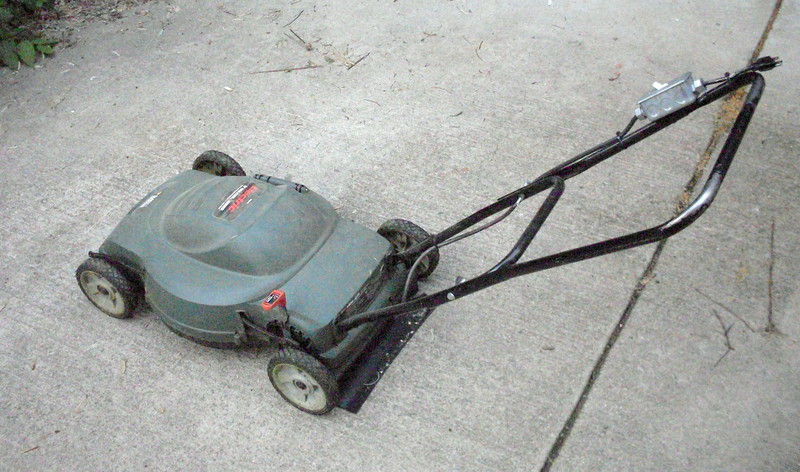
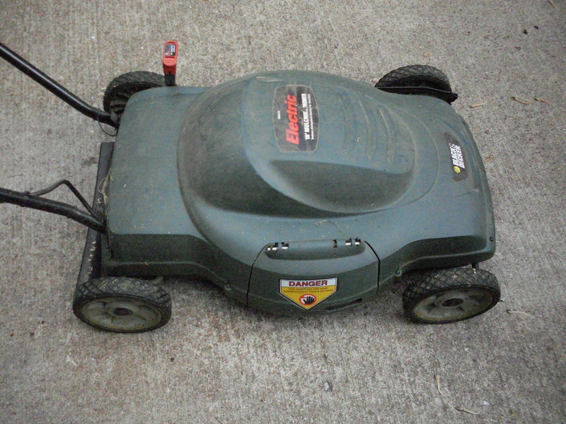
Black & Decker has produced a line of decent corded-electric push mowers (i.e. models LM175, MM275, MM575). My parents and I own a total of 3 of these mowers and really enjoy them. Although they have provided years of good service, like all products they have their weaknesses. This page discusses retrofiting a home-made switch assembly to these mowers.
DISCLAIMER:
This page was created for a specific person and not for public consumption. Therefore it is only provided to you for educational value. This project is NOT considered safe for a variety of reasons...
Performing the following modification(s) will reduce the safety of your mower in at least 2 ways. First, you will not have a "dead-man" style switch, meaning that once on, the mower will run until you switch it off (verses the original behavior of it shutting off when you release the handle). Second, the "plug braking" feature will no longer be used, meaning that the motor and mower blades will take about 7 seconds to spin down to a stop after being turned off (verses stopping in about 1 second). The mower will still otherwise cut grass. Proceed at your own risk! YOU HAVE BEEN WARNED!
Introduction:
Please read the main Electric Lawn Mower Wiring Page first. It provides valuable background information that you should know before reading this page.
If the lawn mower's power switch stops working reliably, you can purchase a replacement switch (i.e. Black & Decker P/N 681064-01) to presumably restore the mower to factory operating condition. Alternatively the stock switch/plug assembly could be replaced with a home-made switch assembly. This page documents one method for building a home-made switch aseembly.
The mower's stock switch assembly can be replaced with standard parts available at most hardware stores. Althought this modification introduces some real safety concers, the overall electrical reliability of the mower should be improved significantly.
Wiring Diagram:
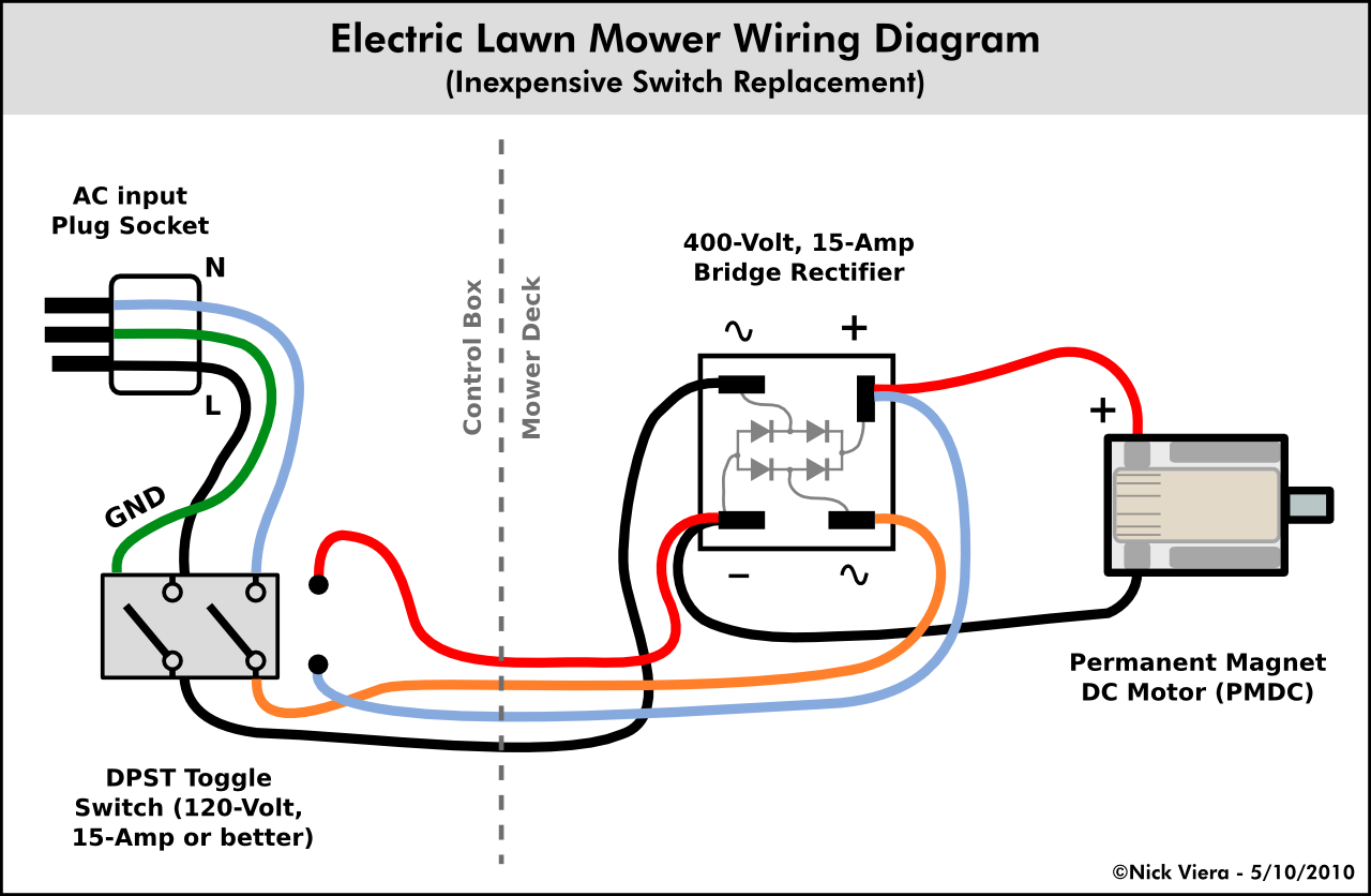
The above diagram shows modifications to the original wiring. Note that the light-blue wires represent white wires, and that the red and white wires from the motor must be capped or taped off (Do not connect them to each other or to anything!)
Part Selection:
Switch Selection
Alternate-action, double-pole switches are difficult to find. Therefore, we are going to replace the stock switch with a standard toggle switch for now (like the kind you see in the walls of buildings). Unfortunately, this means that "plug braking" of the motor will not be possible with a standard-action switch.
The replacement toggle switch could be either a single or double-pole switch. The advantage to using a double-pole switch is that both the "hot" and "neutral" incomming AC lines will be cut when the switch is "off". This is arguably safer than a (less expensive) single-pole switch which only cuts one of the lines because it guarantees that no voltages are present at the motor, regardless of the polarity of the house's AC wiring.
When buying a switch, you are looking for a "commercial grade" switch rated at least 15-Amps and preferably 20-Amps at 120/277-Volts AC. These are quality switches which will tolerate the inductive "kick" that results from switching off the mower's large electric motor. Do not even think about using a cheap $0.49 "residential" grade switch!
Electrical Box Selection
The switch needs to be mounted into a fire-proof electrical box, which in turn can be fastened to the mower's handlebar using zip-ties, bolts, etc. The use of a metal electrical box is recommended over the cheaper plastic boxes because they are more durable. Metal "Handy" boxes, while not water-proof, are a good choice because they are inexpensive, have no sharp edges, and are relatively small in size. Plus, you shouldn't be mowing in the rain anyway!
However, if a metal box is used it absolutely must be electrically grounded using 3-prong cords back to the house's grounding system. If the house does not have a functional grounding system, then STOP RIGHT NOW; this whole retofit could present a shock hazard under the right conditions!
Having said that, in theory using a plastic box and a plastic switch plate will provide a layer of isolation between the operator and the mower's electrical system. Thus, an all plastic switch assembly is arguably safer without any connection to a grounding system than a metal assembly in any configuration. I say arguably because there are of course things that can go wrong either way...
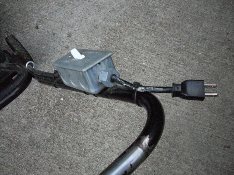
Cordset Selection
In order to bring power into the new switch box, a cordset with the standard NEMA 5-15 male plug on the end is needed. This kind of cordset could be had by cutting the male end off of an extension cord, buying a pre-made NEMA 5-15 to bare wire cordset, buying bulk wire and attaching a NEMA 5-15 plug to the end of it, etc, etc.
Regardless of how a cordset is obtained, it is important that it utilize large enough wire to handle the power draw of the mower. Most of these mowers are rated to pull 13-Amps max. Therefore, per the National Electric Code, the smallest code-compliant wire size the cordset can be is 16AWG. However, a 14AWG cordset should be used to provide a larger safety-margin, especially if the cord is longer than a couple feet.
Materials List:
- 15 or 20-Amp, double-pole "commercial" grade toggle switch
e.g. Cooper Wiring or Leviton part number CS215 or CS220
- Single-gang, metal electrical "Handy" box
e.g. Raco part number 8660 ( < $1 )
- Single-gang, metal "Handy" box switch cover
e.g. Raco part number 865 ( <$1 )
- A 120-Volt, 15-Amp rated plug set (Size 16AWG wire or larger!)
e.g. Something like this one
- (2) 1/2" cord-grip coupler (a type of conduit fitting)
e.g. Sigma Electric part number 49212 ( ~$3 )
Assembly:
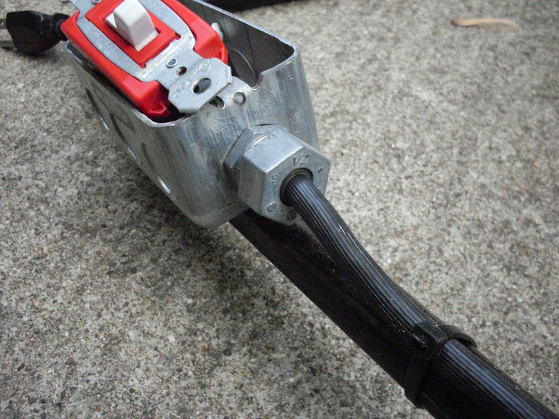
Cord-grip couplers: The first task is to install the cord-grip couplers into the round knockouts in the ends or sides of the electrical box. If a metal box is used, the knockouts can be removed by pushing them inward into the box, and then using pliers to bend them back and forth until they tear off the box. The cord-grip couplers are then inserted through the knockouts and secured using the screw-on rings.
Box Mounting: The Electrical box needs to be mounted to the mower's handlebars.
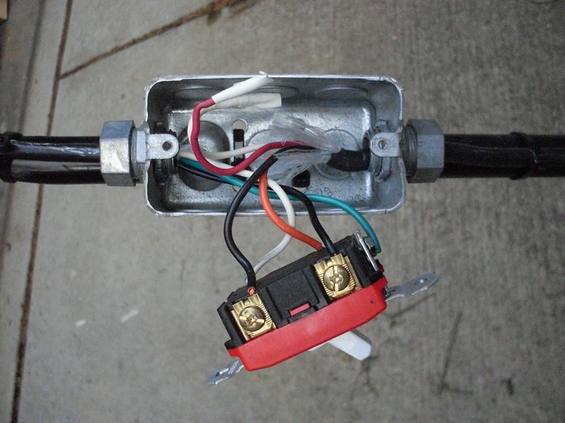
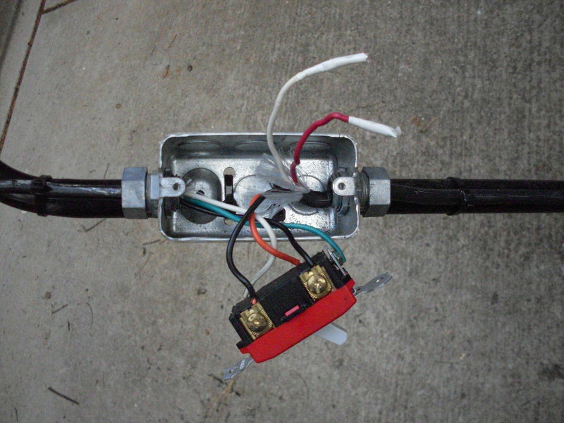
Wires in the Box: The wires from the mower's harness and the cordset need to be stripped and brought into the electrical box, through the loosened cord-grip couplers. After the wires are pulled into the box, tighten the screw nuts on the cord-grips to get them to squeeze down firmly on the wiring. Note that the grips should be gripping the outer sheathing of the wiring, and not the individual wires themselves!


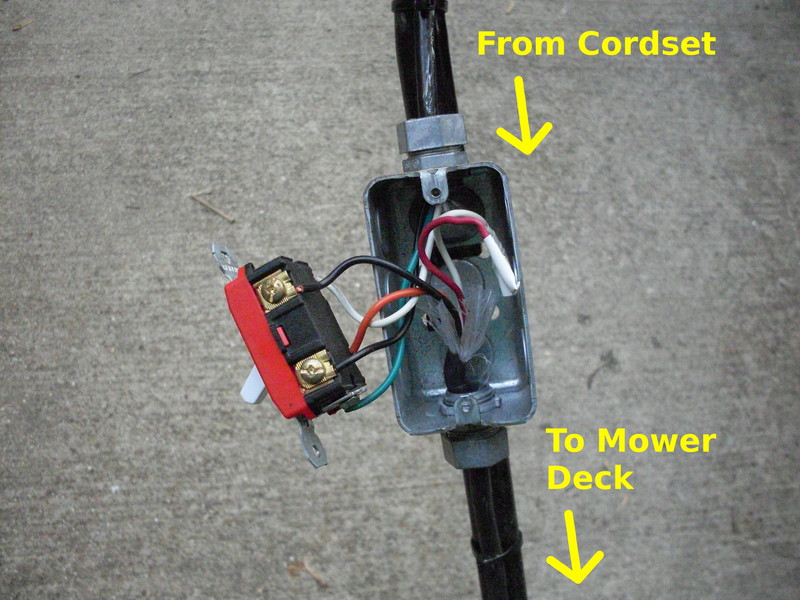
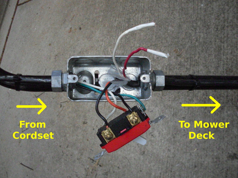
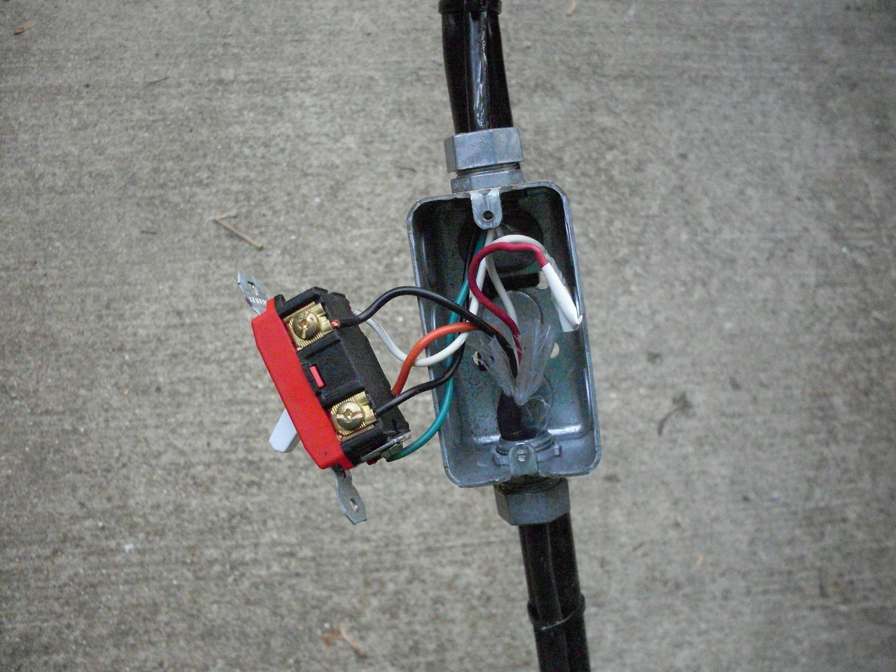
Wiring the new switch in the electrical box
Wiring the Switch: The switch is wired per the wiring diagram near the top of this page. If a double-pole switch is used, the orange and white wires must be connected to the two screw terminals on the one side of the switch, with the two black wires connected to the two screw terminals on the opposite side of the switch. If a single-pole switch is used, only connect the two black wires to the switch's screw terminals, then connect the orange wire from the mower's harness to the white wire from the cordset.
Also, it is generally a good idea to connect the green ground wire from the cordset to the green screw terminal on the switch. Lastly, make sure that the red and white wires from the mower's wiring harness are securely taped off and not connected to anything!
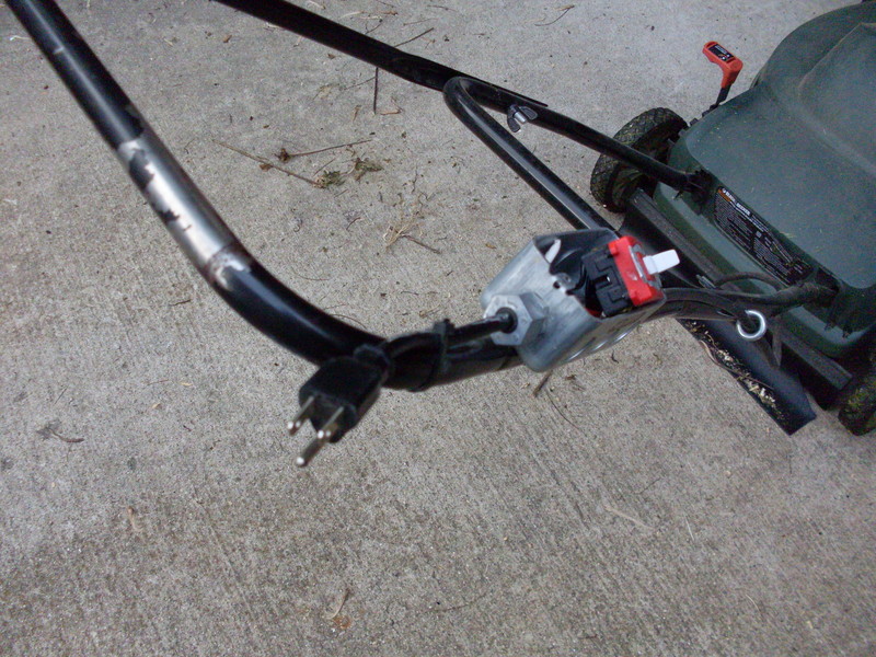
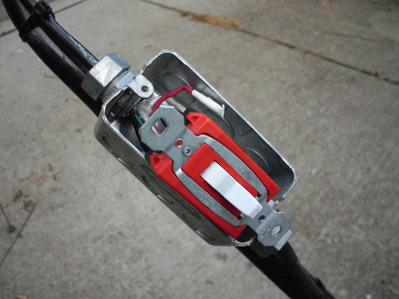
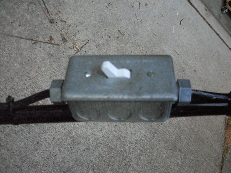
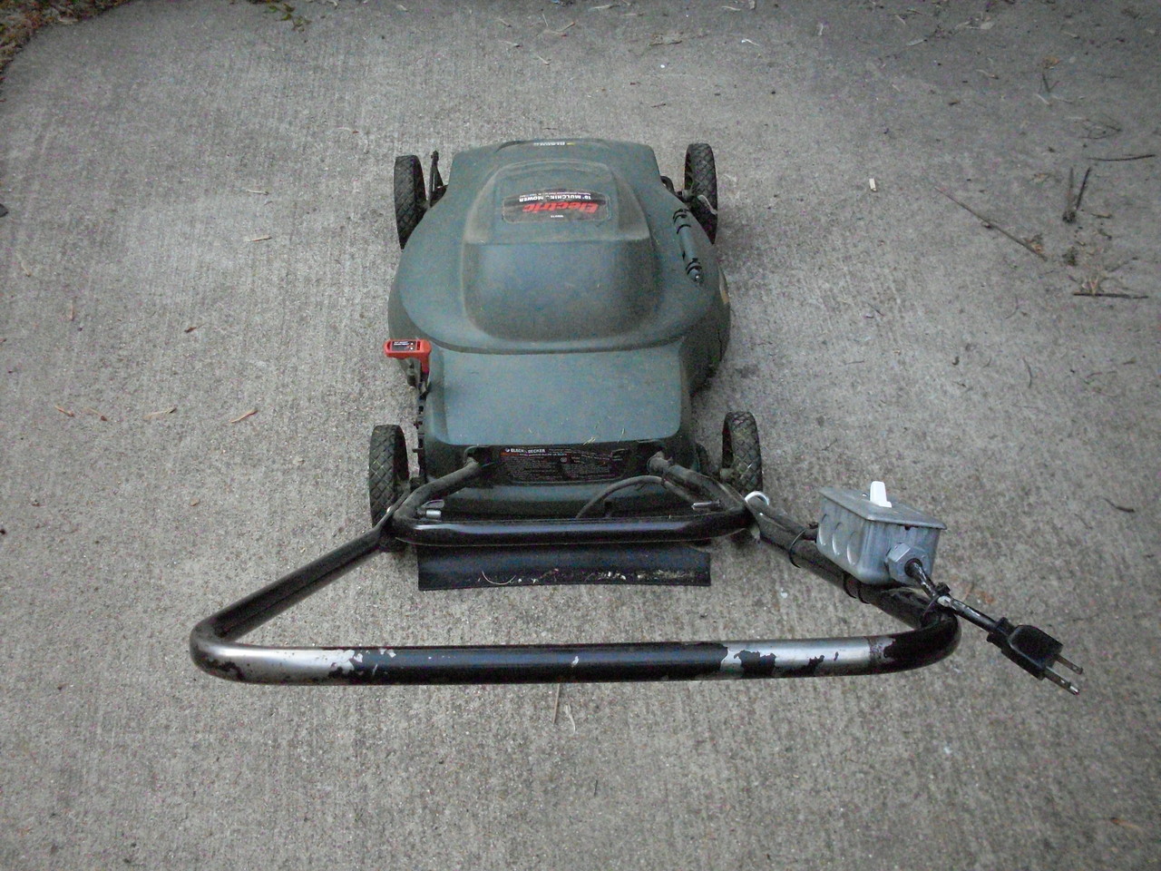
Put it together: The switch should be firmly mounted into the electrical box using the #6 screws provided, and the switch plate should be firmly mounted to the switch also using the provided #6 screws. If everything was done correctly, the mower should run when powered. Otherwise, smoke and/or the tripping of circuit breakers will likely occur.


Finished installation of the new switch and box
All Photos:
|
Electric Mower Switch Modification Photos |
|||
 Large || XL |
 Large || XL |
 Large || XL |
 Large || XL |
 Large || XL |
 Large || XL |
 Large || XL |
 Large || XL |
 Large || XL |
 Large || XL |
 Large || XL |
 Large || XL |
 Large || XL |
 Large || XL |
||
